
Power-on downshift control for a hybrid electric vehicle powertrain

a hybrid electric vehicle and power-on technology, applied in the direction of electric propulsion mounting, dynamo-electric gear control, gear control, etc., can solve the problem of delay in the desired acceleration increase, achieve the effect of improving the quality of the downshift, increasing the acceleration level, and improving the quality

Inactive Publication Date: 2008-03-06
FORD GLOBAL TECH LLC
View PDF13 Cites 18 Cited by
  • Summary
  • Abstract
  • Description
  • Claims
  • Application Information

AI Technical Summary

Benefits of technology

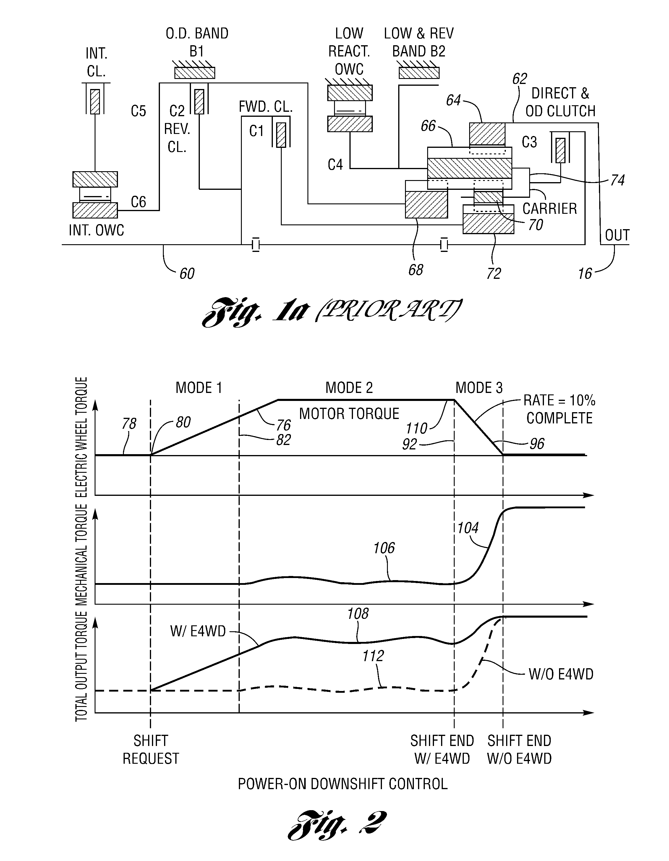
[0012]By adding driving torque at the front traction wheels at the time of a power-on transmission downshift request, the quality of the downshift is improved. This improvement in quality results from an increased level of acceleration that can be provided immediately by adding motor torque to the front traction wheels. There is an immediate response to the driver's demand for acceleration.
[0013]Another feature of the invention is a shortened power-on downshift time that is made possible. This is due to the fact that a power-on downshift normally is calibrated to maintain driveline torque at a pre-shift torque level so that the driver does not experience a decrease in traction wheel torque during progression of the downshift. This normally is accomplished by holding a portion of the capacity of an off-going clutch element in the automatic transmission. This holding torque will slow down the shift by absorbing some of the engine torque that could be used to accelerate the engine. In a powertrain that embodies the present invention, however, the electric motor that drives the front traction wheels can be used to hold total driveline torque such that the rear axle torque can be lowered to permit the shift to occur faster.
[0014]The strategy of the present invention will provide an increased and uniform torque delivery to the traction wheels during a power-on downshift while at the same time reducing shift time.
[0015]The strategy of the present invention is especially effective during power-on downshifts at low vehicle speeds since inertia torque due to changes in speed of rotary powertrain components is lower when the vehicle speed is lower.
[0016]The increased level of acceleration following a driver request for acceleration is achieved by increasing torque output of an electric machine in the electrical power flow path in a first operating mode at the beginning of a power-on downshift, maintaining torque delivered through the transmission at its pre-shift level while a friction element in the transmission is slipping during a second operating mode as torque output of the electric machine remains unchanged, decreasing torque output of the second electric machine in a third operating mode at the end of the power-on downshift, and increasing torque delivered through the mechanical torque delivery elements at the end of the power-on downshift. This provides a fast response to a request for increased traction torque.

Problems solved by technology

This condition causes a delay in the desired acceleration increase.

Method used


Image

  • Power-on downshift control for a hybrid electric vehicle powertrain
  • Power-on downshift control for a hybrid electric vehicle powertrain
  • Power-on downshift control for a hybrid electric vehicle powertrain

Examples


Embodiment Construction

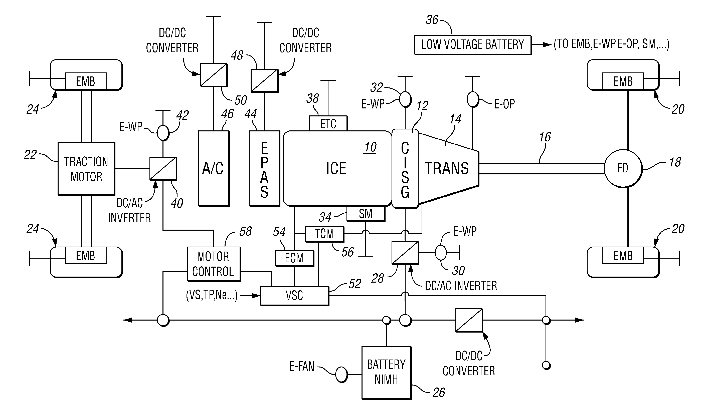
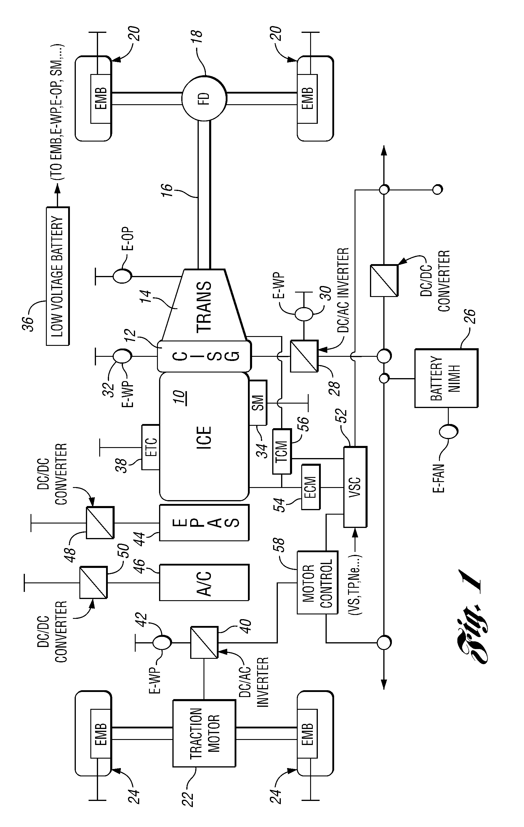
[0023]In the powertrain illustrated in FIG. 1, an internal combustion engine (ICE) is shown at 10. The rotor of a crankshaft-integrated starter-generator (CISG), as shown at 12, is situated between the engine 10 and a multiple-ratio automatic transmission 14. The torque output end of the transmission 14 is connected through a driveline, including driveshaft 16, to a final drive differential-and-axle assembly 18 for delivering torque to traction wheels 20. Unlike the powertrain illustrated in the '066 patent, where a clutch is used to connect the engine crankshaft to the rotor of an electric machine, the rotor of the generator 12 is connected directly to the crankshaft of the engine 10 and to the torque input shaft of the transmission 14.

[0024]A traction motor, which may function as a generator to develop regenerative torque during a vehicle coast mode, is shown at 22. It includes a rotor drivably connected through front axle shafts to front traction wheels 24. Each of the traction w...


PUM


Abstract

A method is disclosed for controlling a hybrid electric vehicle powertrain having a multiple-ratio transmission. On a power-on transmission downshift, electric wheel torque is used to compensate for a slow response of an engine to a request for increased traction wheel torque.

Description

BACKGROUND OF THE INVENTION[0001]1. Field of the Invention[0002]The invention relates to a hybrid electric vehicle powertrain with a multiple-ratio transmission for delivering driving power to vehicle traction wheels.[0003]2. Background Art[0004]Hybrid electric vehicle powertrains for automotive vehicles typically include an internal combustion engine and an electric motor-generator, which define mechanical and electrical driving power sources. One class of hybrid electric vehicle powertrains includes an engine and a motor-generator with gearing in a split power arrangement in which power delivery from each power source to vehicle traction wheels is coordinated to meet a driver demand for power. Such a powertrain arrangement is disclosed in U.S. Pat. No. 6,991,053, which is assigned to the assignee of the present invention. Another class of hybrid electric vehicle powertrains is a so-called dual-drive hybrid electric vehicle powertrain in which an internal combustion engine and a mu...

Claims


Application Information

Patent Timeline
Patent Type & Authority Applications(United States)
IPC IPC(8): B60K1/02
CPCB60K6/44Y10T477/33B60K6/547B60W10/06B60W10/08B60W10/11B60W20/00F16H3/663F16H61/686F16H63/502F16H2061/0433F16H2200/2005F16H2200/2023F16H2200/2046Y02T10/623Y02T10/6265Y02T10/6286Y10T477/23B60K6/52Y02T10/62B60W20/30B60W30/192
Inventor ORTMANN, WALTER
Owner FORD GLOBAL TECH LLC
Learn More