
Apparatus of treating grinding water for processing periphery of eyeglass lens

a technology of grinding water and eyeglass lens, which is applied in the direction of centrifuges, separation processes, filtration separation, etc., can solve the problems of time and labor, water is liable to remain at the inside, and the hand of the operator is liable to become dirty, so as to facilitate the treatment of processing refuses and promote the dewatering efficiency and filtering efficiency of processing refuses.

Active Publication Date: 2008-03-06
NIDEK CO LTD
View PDF5 Cites 1 Cited by
  • Summary
  • Abstract
  • Description
  • Claims
  • Application Information

AI Technical Summary

Benefits of technology

[0005] It is a technical problem of the invention to provide a grinding water treating apparatus capable of easily treating a processing refuse and promoting a dewatering efficiency and a filtering efficiency of a processing refuse.

Problems solved by technology

At this occasion, time and labor are taken and the hand of the operator is liable to become dirty.
Therefore, water is liable to remain at inside thereof, and water is liable to remain also at the taken-out processing refuse.
Further, the grinding water is sprung to outside only from the opening of the center of the lid member, and therefore, the processing refuse is liable to mix with the grinding water.

Method used


Image

  • Apparatus of treating grinding water for processing periphery of eyeglass lens
  • Apparatus of treating grinding water for processing periphery of eyeglass lens
  • Apparatus of treating grinding water for processing periphery of eyeglass lens

Examples


first embodiment

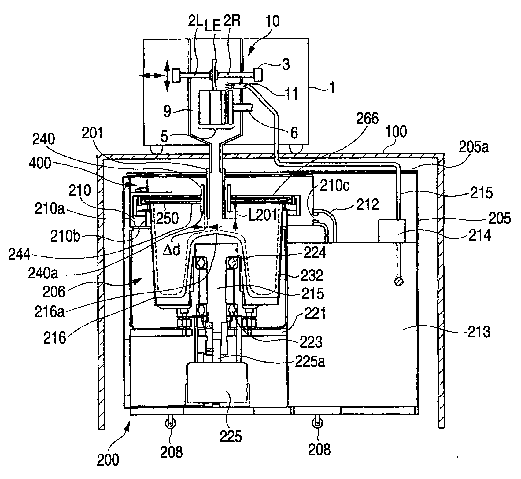
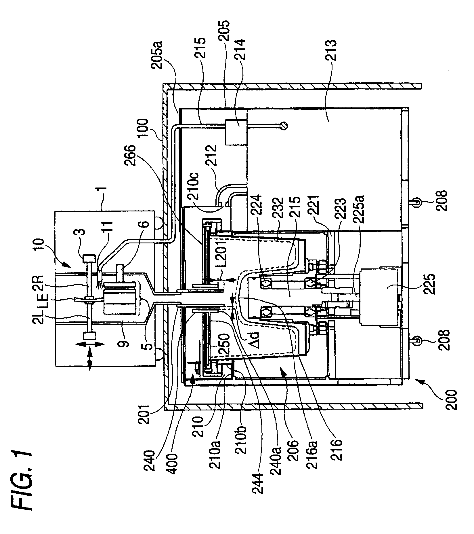
[0035]FIG. 1 is a view showing an outline constitution of a whole eyeglass lens processing apparatus according to the invention. The eyeglass lens processing apparatus includes a processing apparatus main body 1, a table 100 for mounting the main body 1, and a grinding water treating apparatus 200. Further, in FIG. 1 the main body 1 is drawn by being contracted relative to the apparatus 200 for convenience of an explanation.

[0036] Inside of the main body 1 is arranged with a processing mechanism portion 10 including two lens chuck shafts (lens rotating shaft) 2R and 2L holding a processed lens LE, a carriage portion 3 rotatably attached with the chuck shafts 2R and 2L, a grindstone 5 attached to a spindle (rotating shaft) 6 and the like. The carriage portion 3 is constituted lovably in the direction of the chuck shafts 2R and 2L and movably relative to the grindstone 5. Further, with regard to the mechanism portion 10, a constitution of JP-A-H05-21261 by the applicant can be used, ...

second embodiment

[0071] A second embodiment will be explained with reference to FIG. 8 through FIG. 13. FIG. 8 is an outline constitution view of a whole grinding water treating apparatus according to the second embodiment. Constituent elements the same as those shown in FIG. 1 of the first embodiment are attached with the same notations and an explanation thereof will be omitted. FIG. 9 is a view enlarging an essential portion of the centrifugal separator 206 provided to the grinding water treating apparatus.

[0072] In FIG. 9, the rotating shaft 215 arranged at the center of the dewatering tank 216 is extended up to about a half of a height of the dewatering tank 216. Further, the rotating shaft upper surface 216a formed above the rotating shaft 215 is formed at a position higher than the half of the height of the dewatering tank 216. Further, diameters of the rotating shaft 215 and the side portion surface 216b formed therearound are formed to be equal to or larger than ⅓ of the diameter of the de...


PUM

PropertyMeasurementUnit
Centrifugal forceaaaaaaaaaa
Flow rateaaaaaaaaaa
Diameteraaaaaaaaaa

Abstract

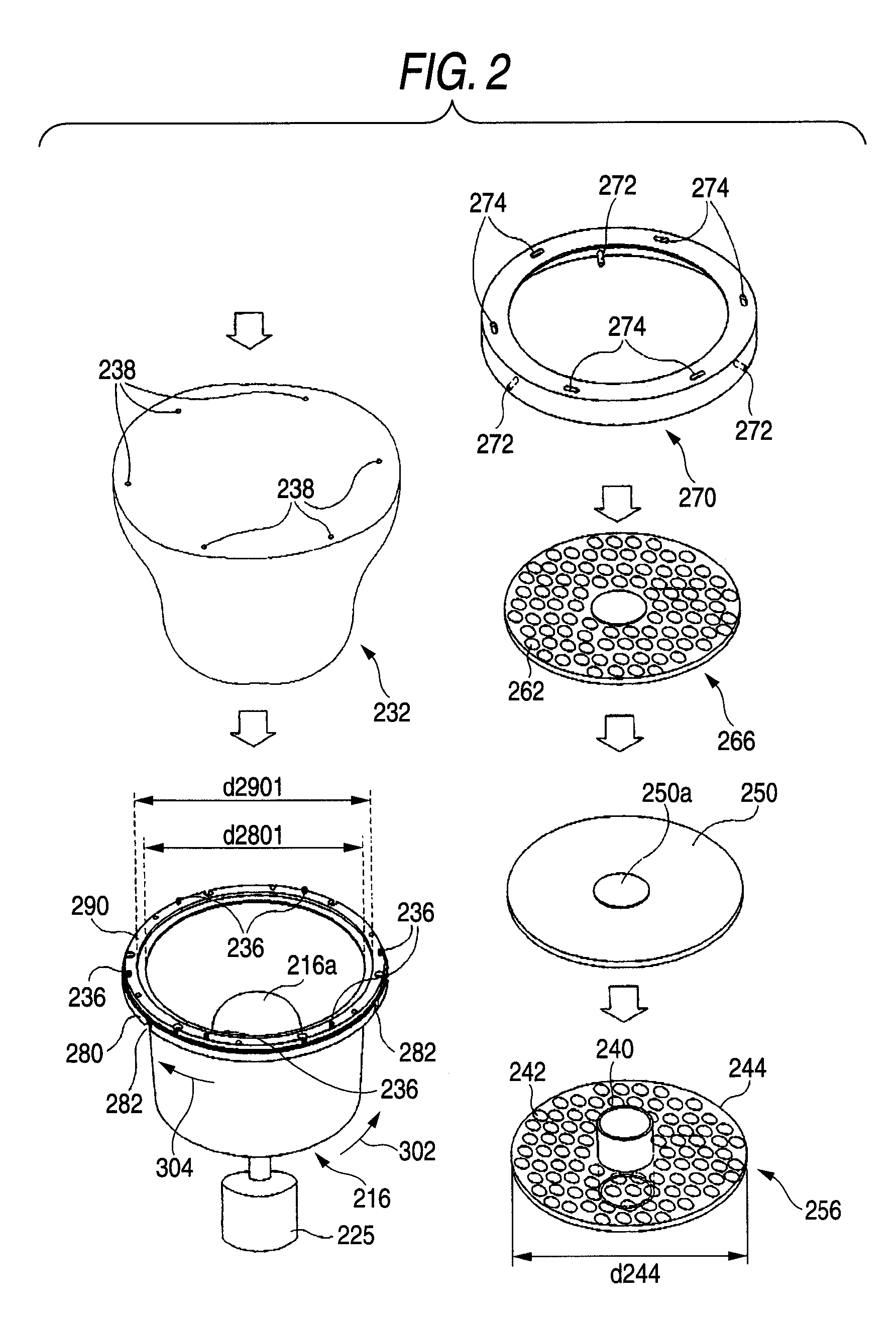
A grinding water treating apparatus for separating a processing refuse from grinding water used for processing a periphery of an eyeglass lens, the grinding water being introduced from an eyeglass lens processing apparatus, the grinding water treating apparatus includes: a centrifugal separator that includes a dewatering tank having a bottom surface and a side surface and a drive source for rotating the dewatering tank, and springs out the grinding water to an upper portion of the dewatering tank by rotating the dewatering tank; and a drain pipe that introduces the grinding water from an upper portion of the dewatering tank. The centrifugal separator includes a filter arranged at the upper portion of the dewatering tank and having an opening inserted with the drain pipe for filtering the grinding water separated from the processing refuse by a centrifugal force generated due to rotation of the dewatering tank.

Description

BACKGROUND OF THE INVENTION [0001] The present invention relates to a grinding water treating apparatus for separating a processing refuse from grinding water discharged from an eyeglass lens processing apparatus to treat the processing refuse. [0002] As an apparatus of treating grinding water for processing an eyeglass lens, there is known an apparatus for separating grinding water and a processing reuse by a centrifugal separator (refer to, for example, JP-A-2002-283236, JP-A-2005-153134). A centrifugal separator described in JP-A-2002-283236 (hereinafter, Patent Reference 1) includes a rotating cylinder as a dewatering tank, and a lid member attached to an upper portion of the rotating cylinder and having an opening at a center of rotation. Further, the centrifugal separator is of a type of springing out grinding water from the opening of the lid member by a centrifugal force. A centrifugal separator described in JP-A-2005-153134 (hereinafter, Patent Reference 2) is of a type of ...

Claims


Application Information

Patent Timeline
IPC IPC(8): B01D29/50
CPCB04B1/02B24B55/03B24B9/14B04B3/00
Inventor TANAKA, MOTOSHINAGURA, AKIHIROINAISHI, KENICHI
Owner NIDEK CO LTD
Learn More