
Catheter and system for using same

a catheter and active technology, applied in the field of catheters, can solve the problems of affecting the clinical and patient experience, affecting the clinical effect of patients,

Inactive Publication Date: 2008-02-28
UNIV OF WESTERN ONTARIO +1
View PDF5 Cites 108 Cited by
  • Summary
  • Abstract
  • Description
  • Claims
  • Application Information

AI Technical Summary

Benefits of technology

The present invention is about a system for controlling a thin flexible thermoplastic catheter. It includes a plurality of shape memory alloy filaments attached to the distal end of the catheter, each filament having a phase and a temperature. The system also includes a means for receiving a strain value for at least one of the filaments, a means for determining the phase change that will result in the strain value, and a means for setting the voltage in each filament thereby resulting in the bending of the catheter. Additionally, the invention includes a three dimensional force sensor attached to the distal end of the catheter, which includes a two-dimensional optical position sensing detector, a spring, an optical fibre embedded within the catheter, and a means for determining the position of the beam spot on the detector. The invention allows for precise control and manipulation of the catheter, which can be useful in various medical procedures.

Problems solved by technology

There are a number of problems associated with the conventional way of performing angioplasty.
The repeated insertion of the catheter through several trials could tear the blood vessel at the junction and cause heavy bleeding.
This could also result in prolonged operating times and fatigue to clinicians and patients.
The surgeon has no method of estimating the amount of force that is being applied by the tip of the catheter on the walls of the blood vessel.
Excessive pressure could rupture the blood vessel with dire consequences.
The healthcare provider could have prolonged exposure to radiation or be subjected to a high-level of noise caused by the machinery generating magnetic fields for MRI.
These pose danger or discomfort to the healthcare providers who perform the procedure over a prolonged period of time.
Another problem with the present procedure of Angioplasty is restenosis.

Method used


Image

  • Catheter and system for using same
  • Catheter and system for using same
  • Catheter and system for using same

Examples


Embodiment Construction

[0034]Researchers in the past have tried to instrument the catheter with Shape Memory Alloy actuators to actively control the tip of the catheter. This way the catheter can be smoothly guided into a branch in the blood vessel. The problem, however, is that the active catheters developed so far consist of actuators without any position feedback. Since most actuators used for the active catheter have a non-linear behavior, the control of the catheter by means of a joy-stick is extremely difficult and inaccurate and could cause damage to the blood vessels.

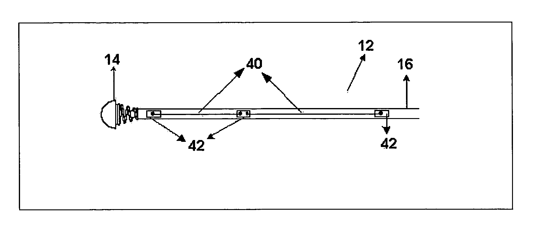
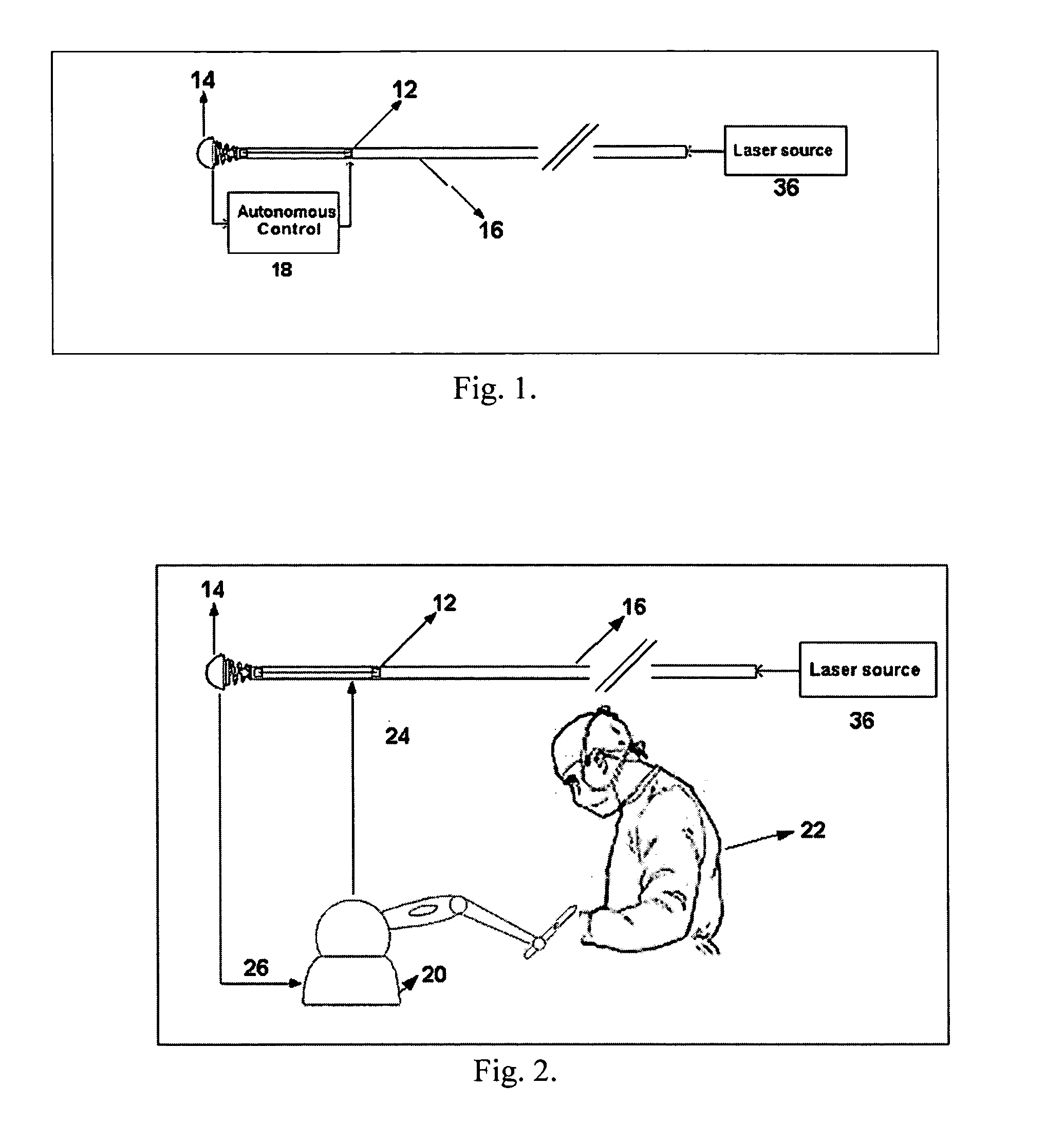
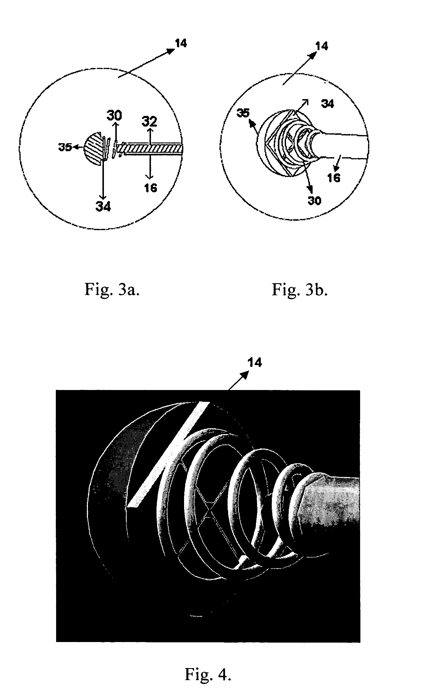
[0035]In one embodiment, this invention describes a completely autonomous control of a catheter instrumented with Shape Memory Alloy (SMA) actuators 12 and a novel three Degree Of Freedom (DOF) force sensor 14 on the tip of the catheter 16, as shown in FIG. 1. The force sensor 14 at the tip measures the magnitude and direction of the force acting on the tip of the catheter 16 due to contact with the blood vessel when used in angioplas...


PUM


Abstract

The present invention describes a system for controlling a thin flexible thermoplastic catheter. The system includes a plurality of shape memory alloy filaments attached to the distal end of the catheter, each filament having a phase and a temperature; a means for receiving a strain value for at least one of the filaments; a means for determining the phase change that will results in the strain value, whereby the phase change is dependent on the temperature and the temperature is dependent on a voltage; and a means for setting the voltage in each filament thereby resulting in movement of the catheter. In addition, a three-degrees of freedom force sensor measures the magnitude and direction of the force exerted on the tip of the catheter. The catheter can be autonomously guided or it can be interfaced to a haptic device. The catheter can also be fitted with microtools.

Description

FIELD OF THE INVENTION[0001]This invention relates to catheters and in particular a haptically controlled active catheter instrumented with shape memory alloy actuators and a three degrees of freedom force sensor.BACKGROUND OF THE INVENTION[0002]Angioplasty is a minimally invasive procedure that involves the insertion of a catheter into the blood vessel for removal of blockages in blood flow. In the conventional approach, the catheter is inserted into the body through the femoral artery and is guided through the lumen of the blood vessel till it reaches a blockage. A stent (superelastic Shape Memory Alloy) is then deployed to open the blood vessel at the blockage and let normal blood flow resume. The surgeon is provided with images that are obtained either by X-ray imaging or by Magnetic Resonance Imaging. These images enable the healthcare provider to track the end point of the catheter (position in absolute coordinates) in real time and determine the future course of insertion.[00...

Claims


Application Information

Patent Timeline
Patent Type & Authority Applications(United States)
IPC IPC(8): A61M31/00A61M37/00
CPCA61L29/04A61M25/0105A61L2400/16A61L29/14A61B2090/064
Inventor PATEL, RAJNIKANT V.JAYENDER, JAGADEESANNIKUMB, SUWAS
Owner UNIV OF WESTERN ONTARIO
Learn More