
Stator field providing torque and levitation

a technology of torque and levitation, which is applied in the field of magnetic bearings, can solve the problems of insufficient starting torque of this type of motor, inability to provide torque and levitation, etc., and achieves simplified electrical control, high damping of harmonics, and simplified construction

Inactive Publication Date: 2005-04-12
LEVITRONIX TECH +1
View PDF13 Cites 82 Cited by
  • Summary
  • Abstract
  • Description
  • Claims
  • Application Information

AI Technical Summary

Benefits of technology

The present invention simplifies the construction of a magnetically journalled machine and its electrical control, which is beneficial. The asymmetrical winding construction improves the stability and accuracy of the position and rotational speed controller, as well as the quietness of the running of the drive system. This is because it reduces the chording of the winding and the associated high damping of harmonics in the field layout and circulation layout.

Problems solved by technology

Both embodiments have considerable technical and economical disadvantages:
The starting weakness of the single-phase drive is brought about by the design.
For many other drive tasks the starting torque of this type of motor is too small.
However the high coil numbers associated with the two rotary field windings are disadvantageous here.

Method used


Image

  • Stator field providing torque and levitation
  • Stator field providing torque and levitation
  • Stator field providing torque and levitation

Examples


Embodiment Construction

A possible embodiment of the invention will be described by way of example in the following.

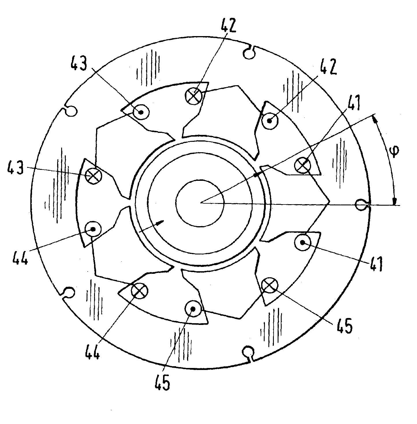
FIG. 4 shows a motor with five concentrated individual coils (41, 42, 43, 44, 45). With this stator arrangement both the two-pole and also a four-pole rotary field, i.e. a two-pole and four-pole MMF, can be achieved at the same time by a corresponding supply of current to the coils with superimposed current components. Thus, in cooperation with the two-poled MMF, torque can be achieved on a two-pole rotor and radial levitation forces can be achieved in cooperation with the four-pole MMF.

The odd number of coils or limbs five, which is not whole-numbered divisible by the two-pole numbers four and two that are used, leads to an asymmetrical stator core and to asymmetrical MMF or field distributions at the periphery of the stator or of the air gap. Accordingly, in dependence on the angular position of the rotor, on the demand for levitation force and on the torque requirement, the coil currents a...


PUM


Abstract

The invention relates to an economical, non-wearing, electrical permanent magnet drive for actively controlling the rotor position in three degree of freedom. The stator windings produce superimposed fields with different pole numbers in the pole pitches by unsymmetrical magnetomotive force distributions.

Description

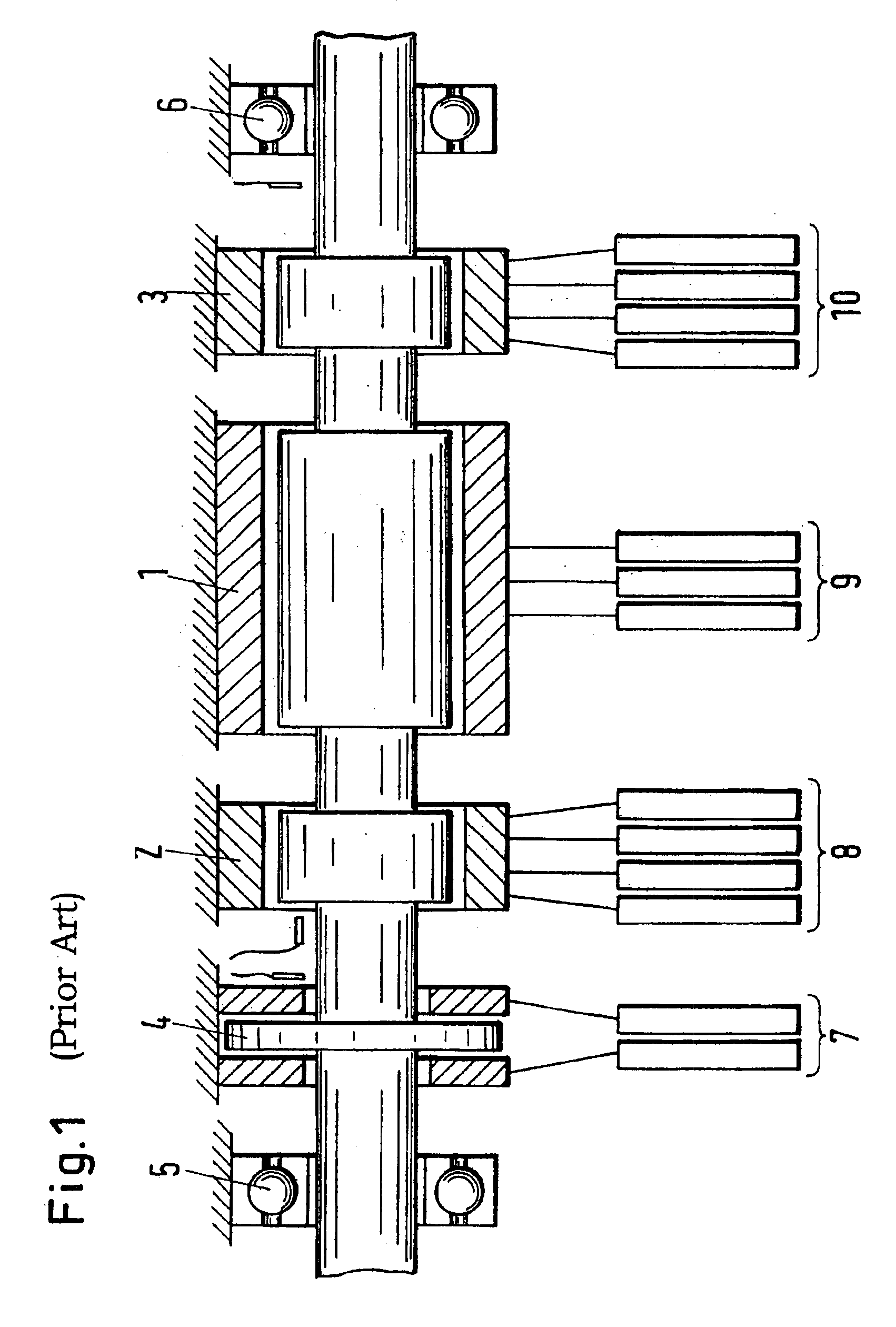
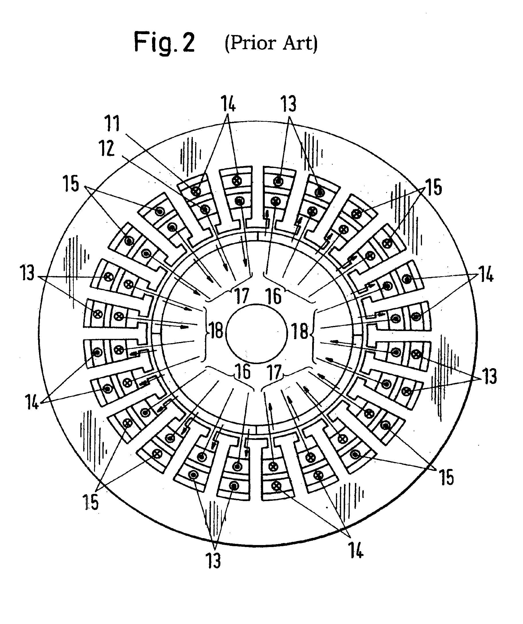
BACKGROUND OF THE INVENTIONThe magnetic bearing technology includes fields of application of machine and apparatus construction with extremely high requirements for the rotary speed range, the working life, the cleanliness and the sealed nature of the drive system—i.e. essentially fields of application which cannot be realized or can only be realized with difficulty using conventional bearing techniques. Various embodiments, such as for example high speed milling and grinding spindles, turbo compressors, vacuum pumps or pumps for high purity chemical or medical products, are already equipped with magnetic bearings.The machine cross-sections shown in the following figures are simply by way of example and partly greatly simplified and serve exclusively for the more precise explanation of the principle of operation.A conventional magnetically journalled machine (FIG. 1) requires, in addition to a machine unit (1), two radial magnetic bearings (2), (3), an axial magnetic bearing (4), tw...

Claims


Application Information

Patent Timeline
Patent Type & Authority Patents(United States)
IPC IPC(8): F16C39/00F16C39/06H02K7/09H02K3/18H02K21/12
CPCH02K7/09F16C32/0493F16C2380/26H02K3/12
Inventor AMRHEIN, WOLFGANGSILBER, SIEGFRIED
Owner LEVITRONIX TECH
Learn More