
Wave Trap

a trap and wave technology, applied in the field of traps, can solve the problems of affecting the safety of ships, and the upper limit of the wave period that those can protect, so as to achieve the effect of efficient attenuation of waves without diminishing water circulation, preventing accidents, and reducing the risk of accidents

Inactive Publication Date: 2008-02-28
ERLINGSSON ULF BIRGER
View PDF6 Cites 17 Cited by
  • Summary
  • Abstract
  • Description
  • Claims
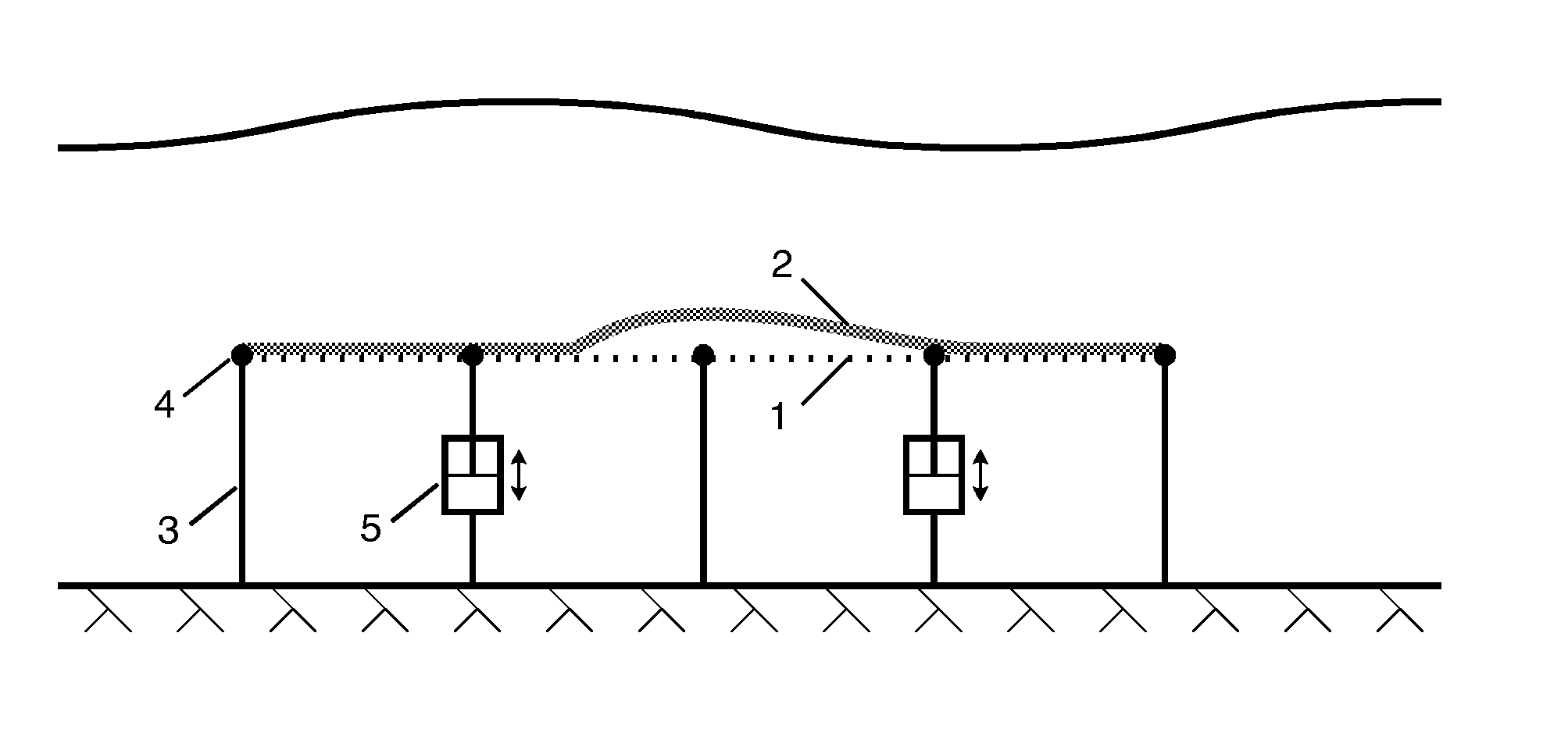
  • Application Information

AI Technical Summary

Benefits of technology

[0009]The challenge is to efficiently attenuate the waves without diminishing the water circulation, without intruding on the beach environment, without hindering navigation and shipping, and in such a way that the wave energy can be converted to useful energy. The goal of the present invention is to both attenuate the waves efficiently and to efficiently convert the attenuated energy to useful energy—and to accomplish this feat with minimal negative environmental impact.
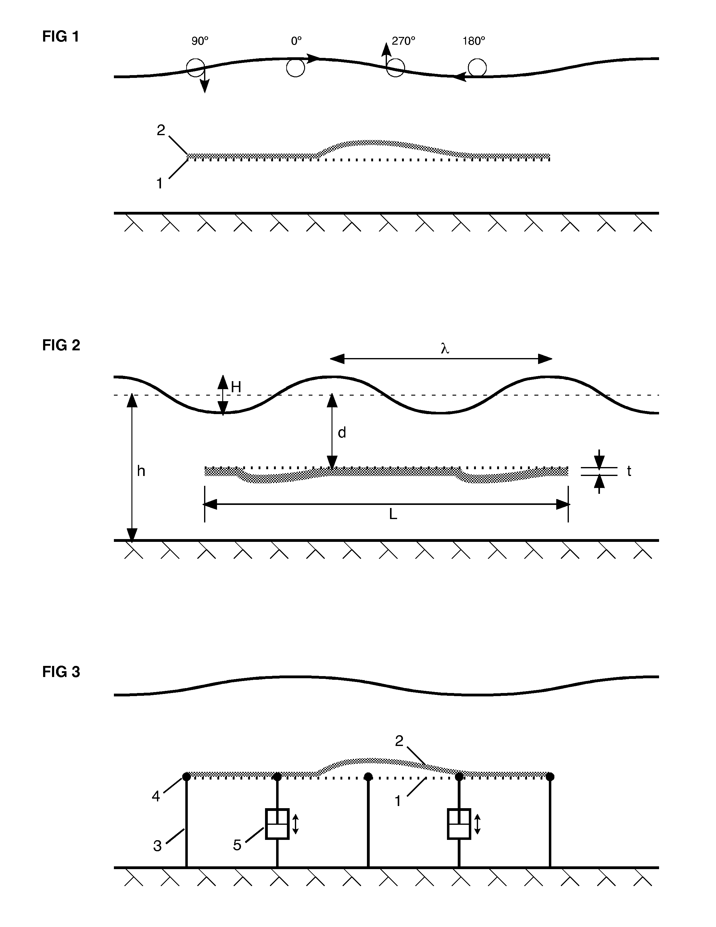
[0010]The invention consists of a horizontal device mounted between the surface and the bottom. It consists of a flexible slab, having a certain combination of submerged weight per area and modulus of elasticity, which rests on a permeable, rigid, and plane net, grid, or equivalent (herein referred to as the plane). The slab can be pushed away from the plane during part of the wave phase, but is stopped in its movement by the plane during the opposite part of the cycle. The pressure that the waves thus exert on the device is converted to forces within its mechanical structure, which can be further converted to commercial energy using known technology. At the same time it has a simple construction and can be built using relatively low-cost materials. Like the flexible membrane it can split the wave period in half, which can make it possible to use a floating breakwater after it for attenuating the remaining smaller waves.

Problems solved by technology

Waves constitute a problem for navigation, especially at loading and unloading sites why these are often placed in a harbor where they are protected by a breakwater.
Floating breakwaters can be used to protect marinas, but there is an upper limit in wave period that those can protect against.
Furthermore waves are a potential threat to infrastructure in the open sea, e.g. drilling and production platforms in oil and gas fields, and terminals for LNG and petroleum products.
Waves may also erode beaches so that onshore infrastructure is endangered.
The intensive building activity on barrier islands and beaches around the world during the past quarter century has therefore led to a dramatic increase in the risk exposure, regardless of whether global warming will lead to a sea-level rise or not.
The former decrease the water circulation, which leads to the loss of bottom biotopes that are very important or even decisive for the marine environment.
The latter destroy the beach environment quite physically, and rip-rap changes the eco-system of the beach permanently.
During strong sea wind some exposed harbors can not be called at due to breaking waves in the harbor entrance.
This renders them useless as ports of refuge for vessels at sea, which is unfortunate since it is precisely during strong sea wind conditions that a port of refuge may be most needed.
Such a breakwater will, however, become quite expensive, and it will significantly limit the water circulation.
The design is, however, quite complex and thus costly for the scale required.
Furthermore it does not lend itself to the generation of renewable energy as a side effect of wave attenuation.
However, they do not attenuate the waves efficiently.
While this can be shown to work empirically, the device is rather expensive to make; and although it is deployed under the surface it has to be placed relatively close to it to be efficient.
Finally, even if it does attenuate the waves the energy is lost as turbulence, and no solution is readily available for incorporating that device in a wave energy conversion system.
Although it may attenuate the waves and split the wave period in half it does not lend itself to be used in a wave energy converter for power generation.
Furthermore a practical and economical implementation of it is difficult due to the nature of the materials and forces required.

Method used


Image

  • Wave Trap
  • Wave Trap
  • Wave Trap

Examples


Embodiment Construction

[0014]The wave energy conversion is accomplished by breaking the orbital motion in the water column during a part of the wave phase, whereby a pressure difference results. Refer to FIG. 1. The device consists of a rigid but permeable plane (1), located approximately horizontally at a depth between the water surface and bottom, upon which a flexible slab (2) rests kept in place by gravitation, and optionally fastening devices, for example ropes, that prevent it from sliding horizontally with the waves. If the slab is heavier than water it is placed above the plane as in FIG. 1, but if it is lighter it is placed below as in FIG. 2.

[0015]When the orbital motion presses the slab away from the plane, as at phase angle 270° in FIG. 1, the slab yields. Since the slab is resting on the underlying water the pressure of the latter increases somewhat. At phase angle 90° the opposite conditions exist; the plane stops the slab so that the orbital motion meets rigid resistance. A relative low pre...


PUM


Abstract

The patent describes a device intended to both attenuate water waves efficiently, and efficiently convert the attenuated energy to useful energy, while having minimal negative environmental impact. The device consists of a flexible slab that rests upon a rigid but permeable horizontal plane between surface and bottom. The slab is alternatively pushed away from the plane, and alternatively it is pressing hard on the plane. The resulting force may be converted to hydraulic energy using established technology. The critical parameters are the submerged weight per area and elasticity of the slab, equations for which are given in the patent.

Description

BACKGROUND OF THE INVENTION[0001]Waves constitute a problem for navigation, especially at loading and unloading sites why these are often placed in a harbor where they are protected by a breakwater. Floating breakwaters can be used to protect marinas, but there is an upper limit in wave period that those can protect against. Furthermore waves are a potential threat to infrastructure in the open sea, e.g. drilling and production platforms in oil and gas fields, and terminals for LNG and petroleum products.[0002]Waves may also erode beaches so that onshore infrastructure is endangered. Both the probability for erosion, and the economical value of the destruction if erosion does occur, increases if there are buildings on the beach. The intensive building activity on barrier islands and beaches around the world during the past quarter century has therefore led to a dramatic increase in the risk exposure, regardless of whether global warming will lead to a sea-level rise or not.[0003]Fro...

Claims


Application Information

Patent Timeline
IPC IPC(8): E02B3/06
CPCE02B3/06Y02E10/38F05B2240/97F03B13/148Y02A10/11Y02E10/30E02B3/062
Inventor ERLINGSSON, ULF BIRGER
Owner ERLINGSSON ULF BIRGER
Learn More