Eureka AIR delivers breakthrough ideas for toughest innovation challenges, trusted by R&D personnel around the world.

Passive acoustic wave sensor system

Inactive Publication Date: 2006-12-21
HONEYWELL INT INC
View PDF22 Cites 43 Cited by
  • Summary
  • Abstract
  • Description
  • Claims
  • Application Information

AI Technical Summary

Benefits of technology

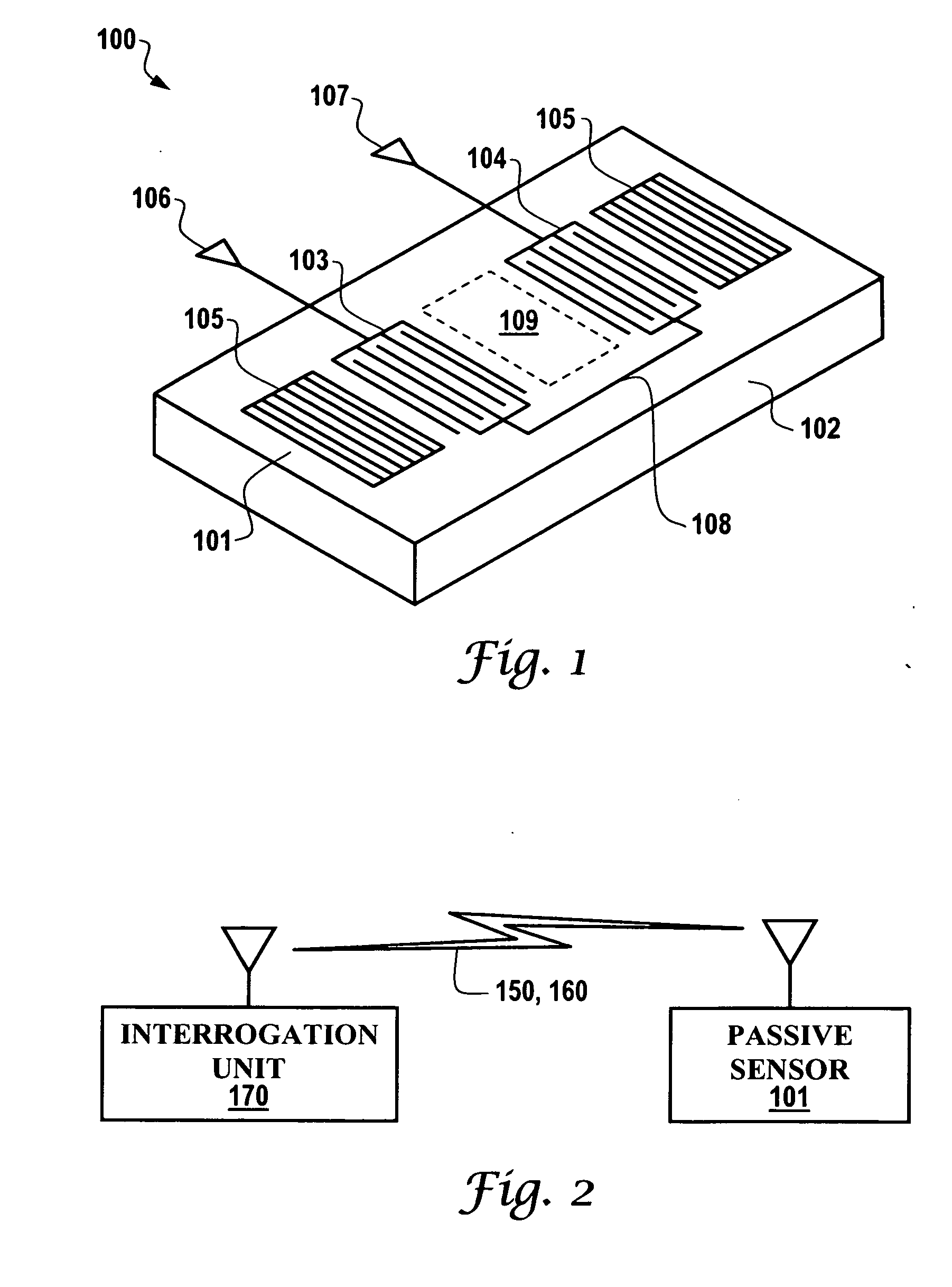
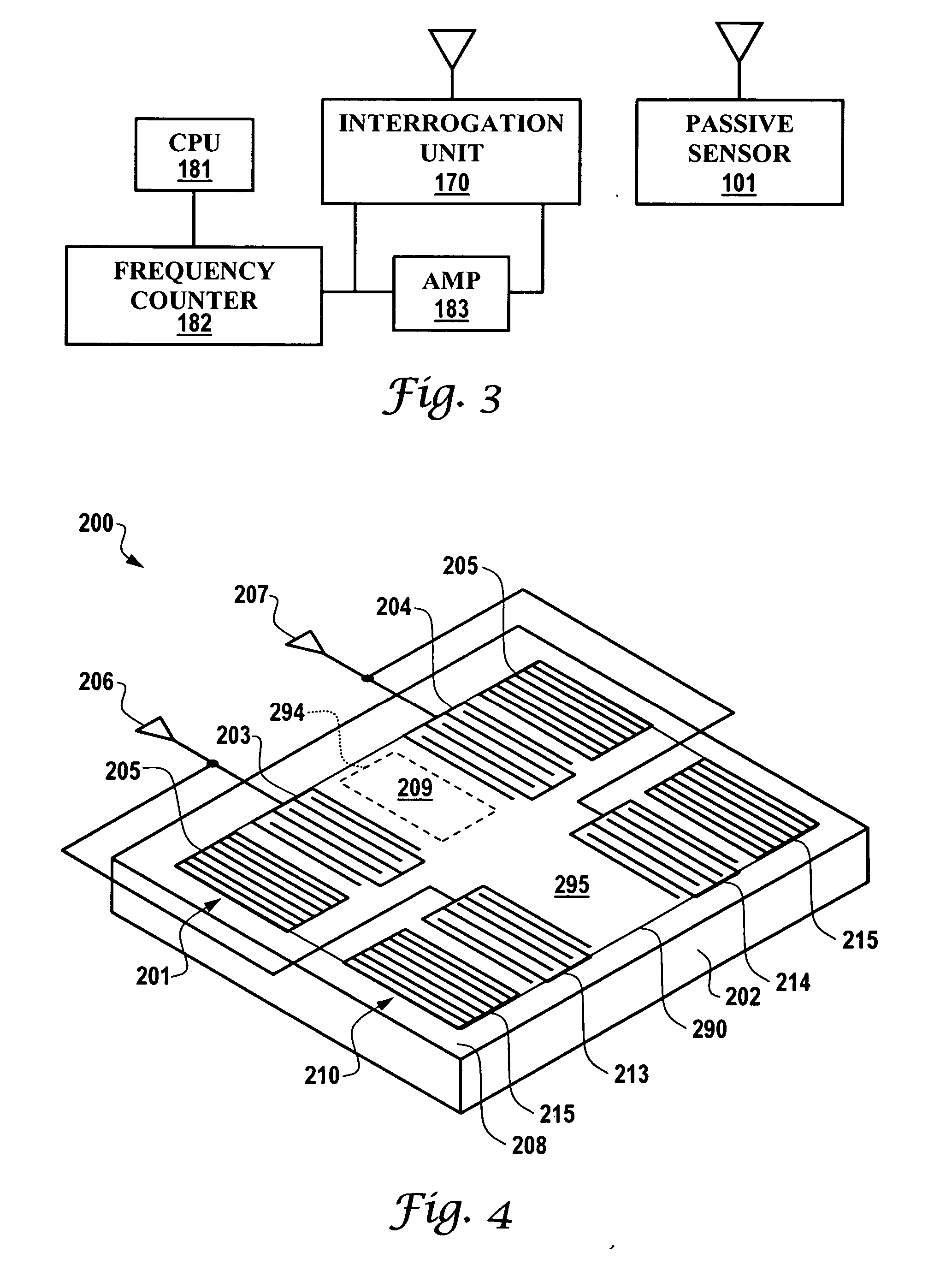
[0024] The sensing device and reference device(s) can be formed on the same side of the substrate such that the interactive and reference regions can contact the liquid under analysis. The reference device(s) and sensing device can include conductive layers disposed on the substrate surface and coupled to the IDTs of the devices. The conductive layer of the sensing device can have an opening defined therein forming an electrically open surface which serves as the sensing device interactive region whereas the conductive layer of each reference device forms an electrically closed surface which serves as the reference device reference region. Utilizing conductive layers in both the sensing device and the reference device(s) allows fabrication of all the devices as a single unit using a small single die. Furthermore, both sensing and reference devices can respond to similar mechanical effects of the liquid and other environmental effects, such as temperature, in a similar manner facilitating compensation of these effects. Alternatively, only each reference device has a conductive layer and the substrate surface between the IDTs of the sensing device can serve as the sensing device interactive region.

Problems solved by technology

Most acoustic wave chemical detection sensors, for example, rely on the mass sensitivity of the sensor in conjunction with a chemically selective coating that absorbs the vapors of interest resulting in an increased mass loading of the SAW sensor.
Diesel engines are particularly hard on oil because of oxidation from acidic combustion.
The frequency changes caused by small changes in viscosity of highly viscous liquids, however, are very small.
Because of the highly viscous loading, the signal from a sensor oscillator is very “noisy” and the accuracy of such measurement systems is very poor.

Method used


Image

  • Passive acoustic wave sensor system
  • Passive acoustic wave sensor system
  • Passive acoustic wave sensor system

Examples


first embodiment

[0055] Since the conductivity of the conductive layer 290 is equivalent to infinity, the electric potential at the interface of the reference region becomes zero such that a reference SH-SAW propagating through the reference device 210 is only perturbed by the mechanical properties of the liquid in contact with the reference region 295 and is unaffected by acousto-electric effects of the liquid. The IDTs 203, 204, 213, 214 and reflectors 205,215 are coated with a thin layer of insulating material to protect them from contacting the liquid, as in the case of the device of the

[0056] The reference device 210 can reply to the interrogation signal 160 by transmitting a response in which mechanical interactions of the liquid with the reference wave are measurable to evaluate the mechanical effects of the liquid on the reference wave. When liquid is in contact with the conductive layer 290 and the interactive region 209, the sensing and reference devices can reply to the interrogation sign...

second embodiment

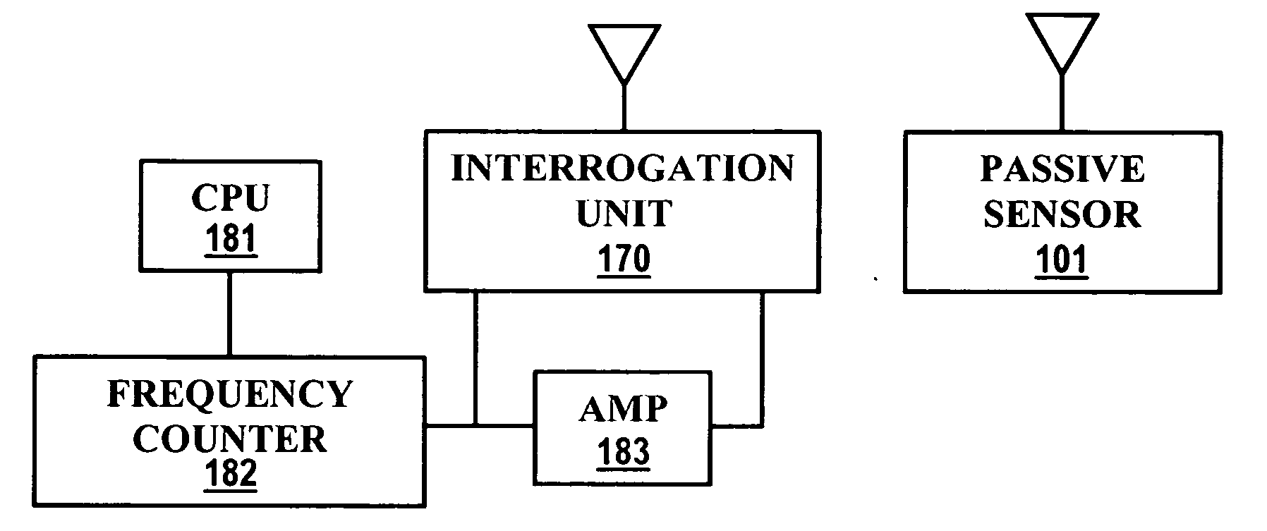
[0057] In this particular embodiment, the outputs responses of the sensing and reference devices 201, 210 are mixed together such that changes in the wave propagation characteristics of each device caused by mechanical effects of the liquid cancel one another leaving only changes caused by the acousto-electric effects of the liquid. Oscillator circuits can be formed by placing the sensing and reference devices in feedback loops of amplifiers and the oscillation frequency can be measured using the same interrogation and processing circuitry shown in FIG. 2. By using a reference device 210 in conjunction with the sensing device 201, the passive sensor system of the second embodiment can more accurately sense electrical properties of oil and other liquids, especially when the liquids are in high concentration and so the mechanical effects of the liquid are more pronounced.

[0058] A method of operating the passive acoustic wave sensor system according to the second embodiment to remotely...

third embodiment

[0060] Referring to FIG. 5(a), which illustrates a passive sensor system having a sensing device and a pair of reference devices a pair of reference devices 310, 320 are utilized to enable temperature or other environmental effects which influence the oscillation frequency of the devices to be monitored allowing temperature or other environmental compensation of the measurements of changes in frequency caused by the acousto-electric and / or the mechanical effects of the liquid. In this particular embodiment, the reference devices 310, 320 are for providing temperature compensation.

[0061] Each of the reference devices is similar to the reference device 210 of the second embodiment and each forms an oscillation loop with an amplifier. However, since the temperature coefficient of the SAW velocity is dependent on the propagation direction on the substrate, the reference devices have a specific angle arrangement and topology such that the reference devices oscillate on slightly differen...


PUM


Abstract

A passive acoustic wave sensor system for monitoring the quality of liquids, such as engine oil, is disclosed. The sensor system has an acoustic wave sensing device for generating a propagating acoustic wave and for detecting changes in frequency or other propagation characteristics of the acoustic wave caused by acousto-electric interactions between the liquid and the wave at an interactive region of the device. An antenna is integrated in the sensing device for receiving an interrogation signal and for transmitting the output response of the sensing device. The output response can be analyzed to determine the conductivity, pH or other electrical characteristics of the liquid. One or more reference devices may be utilized to compensate for mechanical effects of the liquid and temperature or other environmental effects. The sensing and reference devices can be configured as SH-SAW, SH-APM, FPM devices or other acoustic wave devices.

Description

TECHNICAL FIELD [0001] Embodiments are generally related to sensing devices, systems and methods and, in particular, to acoustic wave sensor devices, systems and methods. Embodiments are additionally related to passive acoustic wave sensor devices, such as, for example, surface acoustic wave (SAW) devices and sensors. Embodiments are additionally related to sensors for monitoring the electrical properties of oil and other liquids. Additionally, embodiments are related to detection of the pH of engine oil contained inside an oil filter system of a vehicle. BACKGROUND OF THE INVENTION [0002] Acoustic wave sensors are utilized in a variety of sensing applications, such as, for example, temperature and / or pressure sensing devices and systems. Acoustic wave devices have been in commercial use for over sixty years. Although the telecommunications industry is the largest user of acoustic wave devices, they are also used for sensor applications, such as in chemical vapor detection. Acoustic...

Claims


Application Information

Patent Timeline
IPC IPC(8): G01N29/00
CPCG01N29/022G01N29/2462G01N29/30G01N29/4436G01N2291/0226G01S13/755G01N2291/0422G01N2291/0423G01N2291/0427G01N2291/045G01N2291/0256G01N29/02G01S13/75
Inventor LIU, JAMES ZTRHODES, MICHAEL L.RAHMAN, AZIZ
Owner HONEYWELL INT INC
Why Eureka
Eureka Blog
Learn More