
Optimized analytical method and system for noise control in transformer station

A technology of noise control and analysis method, applied in the direction of electrical digital data processing, special data processing applications, instruments, etc., can solve the problems of sound energy attenuation, sound waves cannot directly reach the receiving point, etc., to promote health, avoid blindness, The effect of improving the noise control effect

Active Publication Date: 2011-09-21
STATE GRID CHONGQING ELECTRIC POWER CO ELECTRIC POWER RES INST +1
View PDF2 Cites 41 Cited by
  • Summary
  • Abstract
  • Description
  • Claims
  • Application Information

AI Technical Summary

Benefits of technology

This patented technology helps calculate optimal sound barries that minimizes interference from different noisy areas by analyzing factors like atmospheric conditions or land use patterns. These optimizations help reduce unwanted sounds while still providing good noise reduction performance across various types of noise source locations. Additionally, these systems provide visual feedback during operation allowing operators to monitor their environment's impact on other nearby units without having them be affected. Overall, they aim to enhance energy management and protect against pollution caused by industrial activities.

Problems solved by technology

This patented technical problem addressed in this patents relates to improving the efficiency and effectiveness of reducing noise emissions (noise) within indoor environments without compromising their physical integrity. Current methods involve either optimizing placement of acoustic barriers based solely upon these issues alone, but they often result in overlapping coverage zones where multiple sounds may exist simultanously. Therefore, it becomes necessary to develop a new approach that considers both environmental factors like ambient lighting levels and terrain features while considering the importance of each factor separately.

Method used


Image

  • Optimized analytical method and system for noise control in transformer station
  • Optimized analytical method and system for noise control in transformer station
  • Optimized analytical method and system for noise control in transformer station

Examples


Embodiment Construction

[0054] Hereinafter, preferred embodiments of the present invention will be described in detail with reference to the accompanying drawings. It should be understood that the preferred embodiments are only for illustrating the present invention, but not for limiting the protection scope of the present invention.

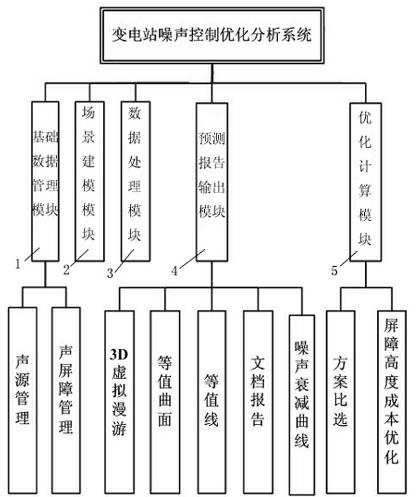
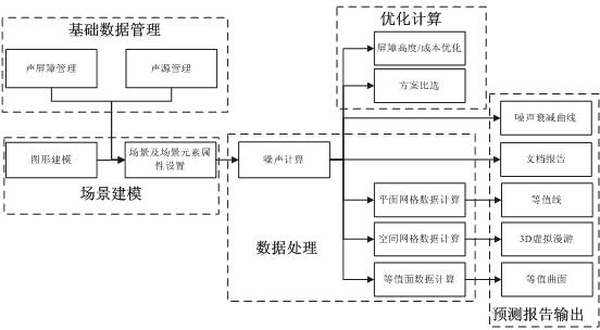
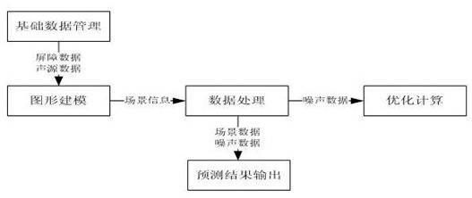
[0055] like figure 1 As shown, the substation noise control optimization analysis system of the present invention includes a basic data management module 1, a scene modeling module 2, a data processing module 3, a forecast report output module 4 and an optimization calculation module 5; wherein,

[0056] 1) The basic data management module is used to manage the sound source / sound barrier database, including the establishment of the sound source / sound barrier database, the import of basic data, and the deletion, modification and maintenance of basic data; in this embodiment, the Basic data include structure location data, noise source location data, and sound pressure ...


PUM


Abstract

The invention discloses an optimized analytical method for noise control in a transformer station. The optimized analytical method comprises the following steps of: (1) collection of basic data; (2) establishment of a physical model; (3) calculation of the value of noise at a receiving point; (4) judgment of limit values; (5) optimization analysis; and (6) selection of an optimal scheme. By adopting the optimized analytical method, the geometric divergence of noise transmission and the influence of atmosphere, ground, buildings, green belts and the like on noise attenuation in transmission routes can be accurately taken into consideration, therefore the magnitude of noise at arbitrary point in a transformer station or the space surrounding the transformer station can be accurately predicted, a more quick and effective design reference is provided for noise control engineering in the transformer station, and the noise of the transformer station at the preliminary stage of design can becontrolled to the extent of minimum impact on the environment; at the same time, an optimal sound barrier design scheme for the noise control of the transformer station can be obtained, the noise control effect is improved, the environment-friendliness requirements are better satisfied, the construction cost is lowered, and the blindness during noise control is avoided. In addition, the inventionalso provides an optimized analytical system for noise control in the transformer station.

Description


Claims


Application Information

Patent Timeline
Owner STATE GRID CHONGQING ELECTRIC POWER CO ELECTRIC POWER RES INST
Learn More