Eureka AIR delivers breakthrough ideas for toughest innovation challenges, trusted by R&D personnel around the world.

Linear-predict sampling for measuring demagnetized voltage of transformer

a transformer and demagnetized voltage technology, applied in the control circuit of a switching power converter, process and machine control, electric variable regulation, etc., can solve the problems of poorer regulation of the power converter, inability to accurately measure the voltage signal of the transformer, and complicated detection circuits of the aforementioned prior art, so as to achieve simple and more precise results

Active Publication Date: 2008-02-21
FAIRCHILD SEMICON CORP
View PDF11 Cites 60 Cited by
  • Summary
  • Abstract
  • Description
  • Claims
  • Application Information

AI Technical Summary

Benefits of technology

"The present invention provides a simpler and more precise sampling circuit to measure the demagnetized voltage of a transformer. This demagnetized voltage is used to generate a feedback signal for a power converter, which is then regulated to output a desired voltage. The invention uses a signal-generation circuit to generate a sample signal based on a first signal, a second signal, and the switching signal. The first signal is correlated to the magnetized voltage of the transformer, while the second signal is correlated to the demagnetized voltage of the transformer. A sample-and-hold circuit is also used to generate the feedback signal by sampling the demagnetized voltage of the transformer in response to the sample signal. This feedback signal is then correlated to the output voltage of the power converter. Overall, the invention provides a more accurate and efficient means to measure the voltage of a transformer in a power converter."

Problems solved by technology

However, the skill of the aforementioned prior art cannot measure an accurate voltage signal from the transformer.
Therefore, a poorer regulation of the power converter is resulted.
But the detection circuits of the aforementioned prior arts are too complicated, which increases the cost of the power supply.

Method used


Image

  • Linear-predict sampling for measuring demagnetized voltage of transformer
  • Linear-predict sampling for measuring demagnetized voltage of transformer
  • Linear-predict sampling for measuring demagnetized voltage of transformer

Examples


Embodiment Construction

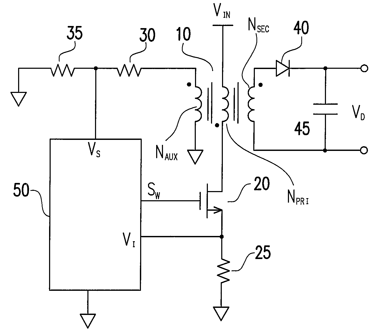
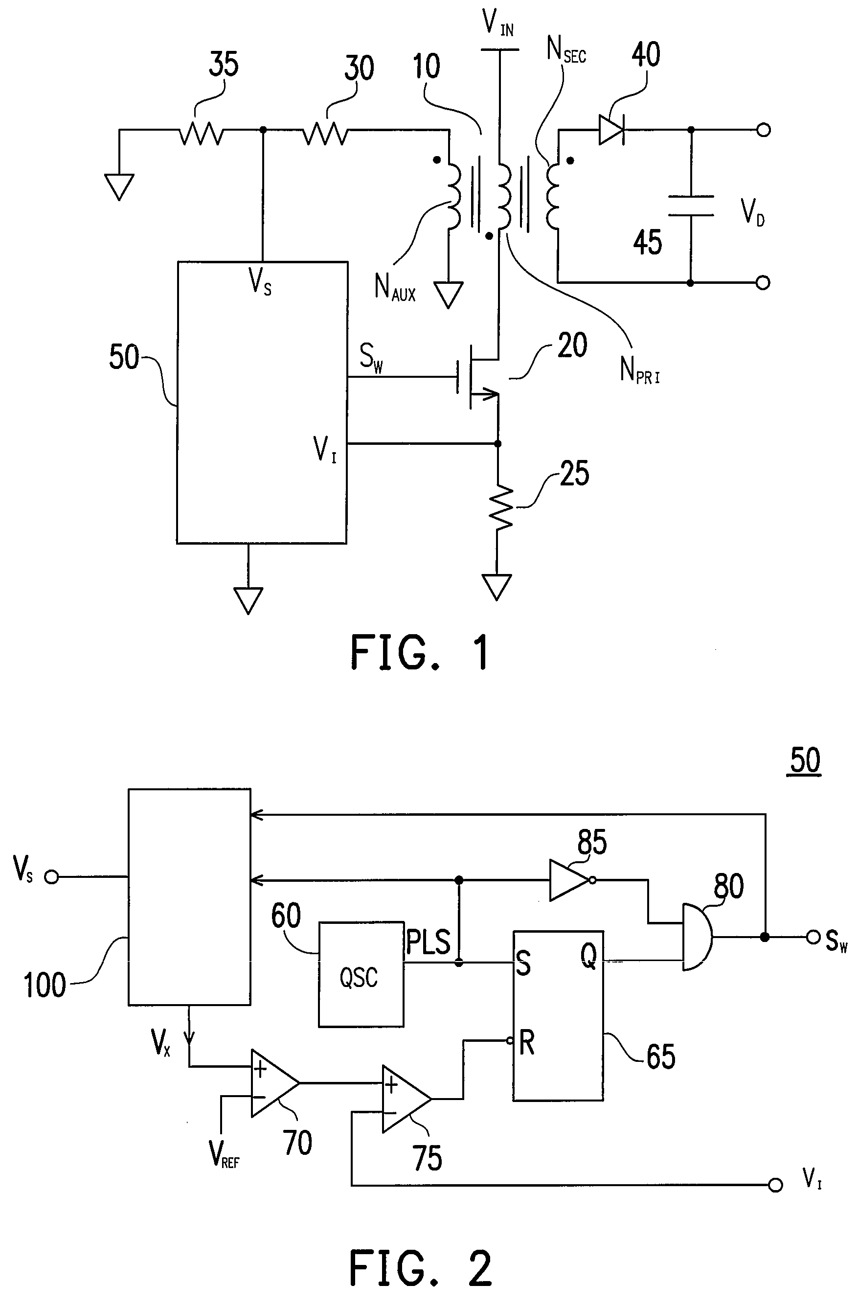
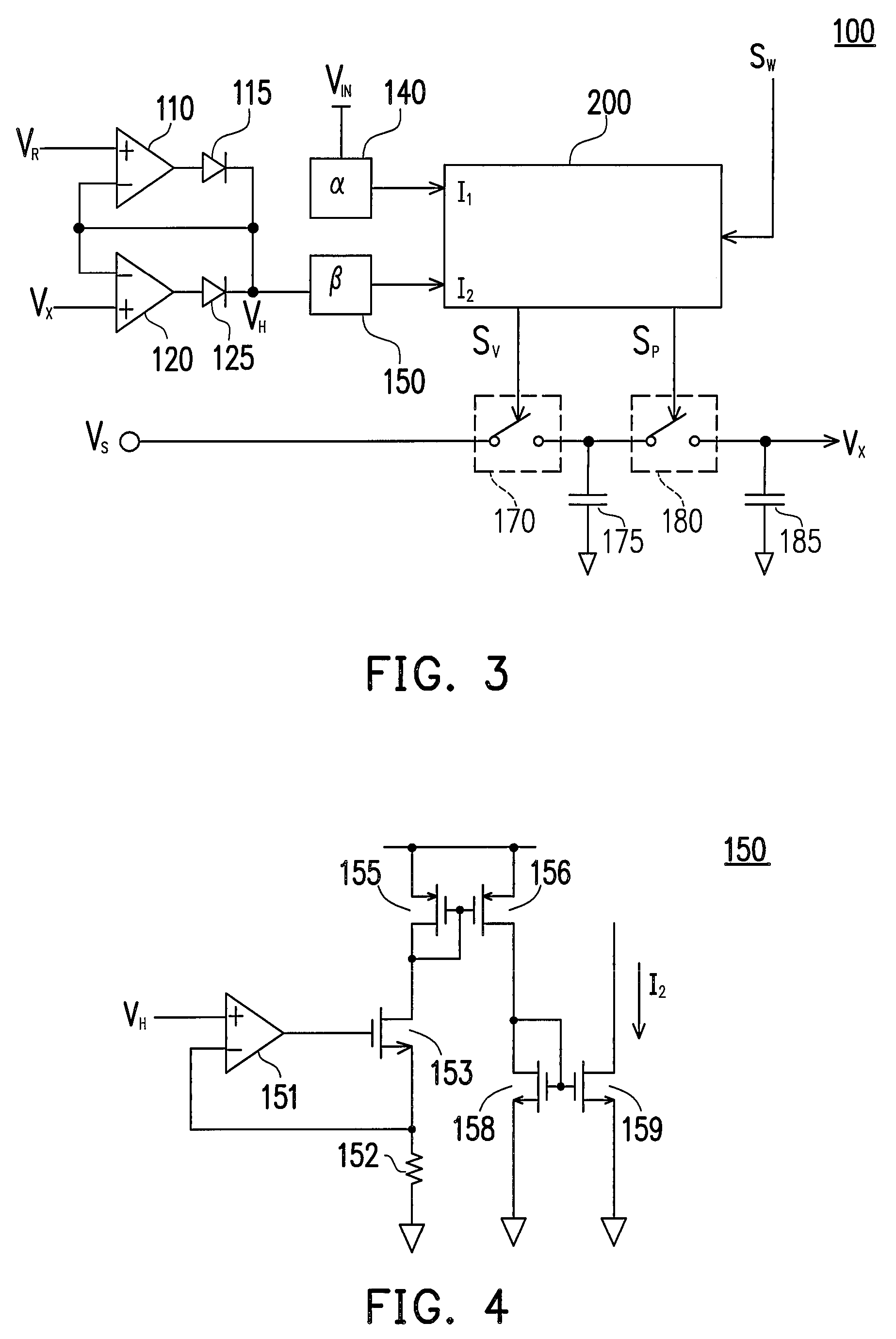
[0014]FIG. 1 shows a switching power converter, according to a preferred embodiment of the present invention, comprising a transformer 10 having an auxiliary winding NAUX, a primary winding NPR1, and a secondary winding NSEC. The primary winding NPR1 is coupled to an input voltage VIN. The secondary winding NSEC generates an output voltage VO via a rectifier 40 and a capacitor 45. In order to regulate the output voltage VO, a switching control circuit 50 generates a switching signal SW to switch the transformer 10 via a transistor 20. When the transistor 20 is turned on, a magnetized voltage, which is equivalent to the input voltage VIN, is applied to the transformer 10. A charge current is therefore flowed through the primary winding NPR1 of the transformer 10 and the transistor 20. Through a resistive device 25, the charge current is converted to a current signal coupled to a VI terminal of the switching control circuit 50. The energy stored into the transformer 10 during a magnet...


PUM


Abstract

A linear-predict sampling circuit is developed to generate a feedback signal by detecting a demagnetized voltage of the transformer. A switching signal is generated in response to the feedback signal for regulating the output of the power converter. A signal-generation circuit is used to generate a sample signal in response to a first signal, a second signal, and the switching signal. The first signal is correlated to a magnetized voltage of the transformer. The second signal is correlated to the demagnetized voltage of the transformer. A sample-and-hold circuit is coupled to the transformer to generate the feedback signal by sampling the demagnetized voltage of the transformer in response to the sample signal. The feedback signal is correlated to the output voltage of the power converter.

Description

BACKGROUND OF THE INVENTION[0001]1. Field of the Invention[0002]The present invention relates to a power converter, and more specifically relates to a control circuit of a switching power converter.[0003]2. Description of Related Art[0004]Power supplies have been widely used to provide regulated output voltages. For the sake of safety, an off-line power supply must provide isolation between its primary side and secondary side. An optical-coupler and a secondary-side regulator are needed to regulate the output voltage of the off-line power supply. In order to reduce the device count and the secondary-side feedback circuit, the demagnetized voltage of the transformer had been utilized to regulate the output voltage of the power supply, such as described in “Rectifier-converter power supply with multi-channel flyback inverter”, by Randolph D. W. Shelly, in U.S. Pat. No. 4,302,803. However, the skill of the aforementioned prior art cannot measure an accurate voltage signal from the tran...

Claims


Application Information

Patent Timeline
Patent Type & Authority Applications(United States)
IPC IPC(8): H02M3/335
CPCH02M3/33507
Inventor YANG, TA-YUNG
Owner FAIRCHILD SEMICON CORP
Why Eureka
Eureka Blog
Learn More