
Bio tank/oxygen replenishment system

a bio-tank and oxygen replenishment technology, which is applied in the direction of water/sewage treatment by flotation, feed/discharge of settling tanks, trickle coolers, etc., can solve the problems of large tanks, high cost of subsequent cleaning, and slow process, and achieve the effect of easy separation from water

Active Publication Date: 2008-02-21
WORLD WATER TECH
View PDF7 Cites 19 Cited by
  • Summary
  • Abstract
  • Description
  • Claims
  • Application Information

AI Technical Summary

Benefits of technology

"The present invention is a system for treating contaminated liquid, such as wastewater, by using a bio-tank for further decontamination. The system includes a pre-treatment for removing large particles, fats, grease, and other organic materials. Membrane separation, such as nanofiltration or reverse osmosis, is also used to remove non-biodegradable organic materials and inorganic ions. An oxygen probe measures real-time oxygen concentrations in the wastewater and a controller regulates the oxygen replenishment rate based on the measurements. The system also includes a mixer for mixing the wastewater and oxygen, an accelerator head, a down tube, and a conduit for selective reintroduction of oxygen. The system can also be coupled with a holding tank, a dissolved air flotation system, and a liquid-solid mixer for removing larger particles. The technical effects of the invention include efficient oxygen replenishment, improved wastewater treatment, and reduced carbon dioxide and suspended solids production."

Problems solved by technology

But, subsequent cleaning is expensive and often is inefficient as the membranes get fouled with various species present in water.
But, this process is slow and consequently requires large tanks.
Anaerobic degradation is generally efficient, but, it can take months or even years to destroy biodegradable organic pollutants.
Low organic loads can upset the biological aerobic wastewater treatment process.
Unfortunately, most industrial wastewater is rich in nutrients and continuity varies in composition.

Method used


Image

  • Bio tank/oxygen replenishment system
  • Bio tank/oxygen replenishment system
  • Bio tank/oxygen replenishment system

Examples


Embodiment Construction

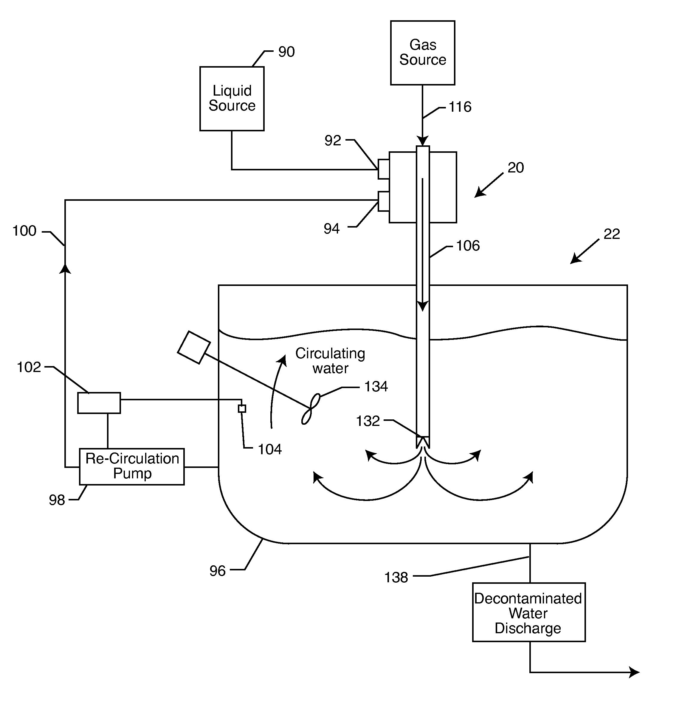
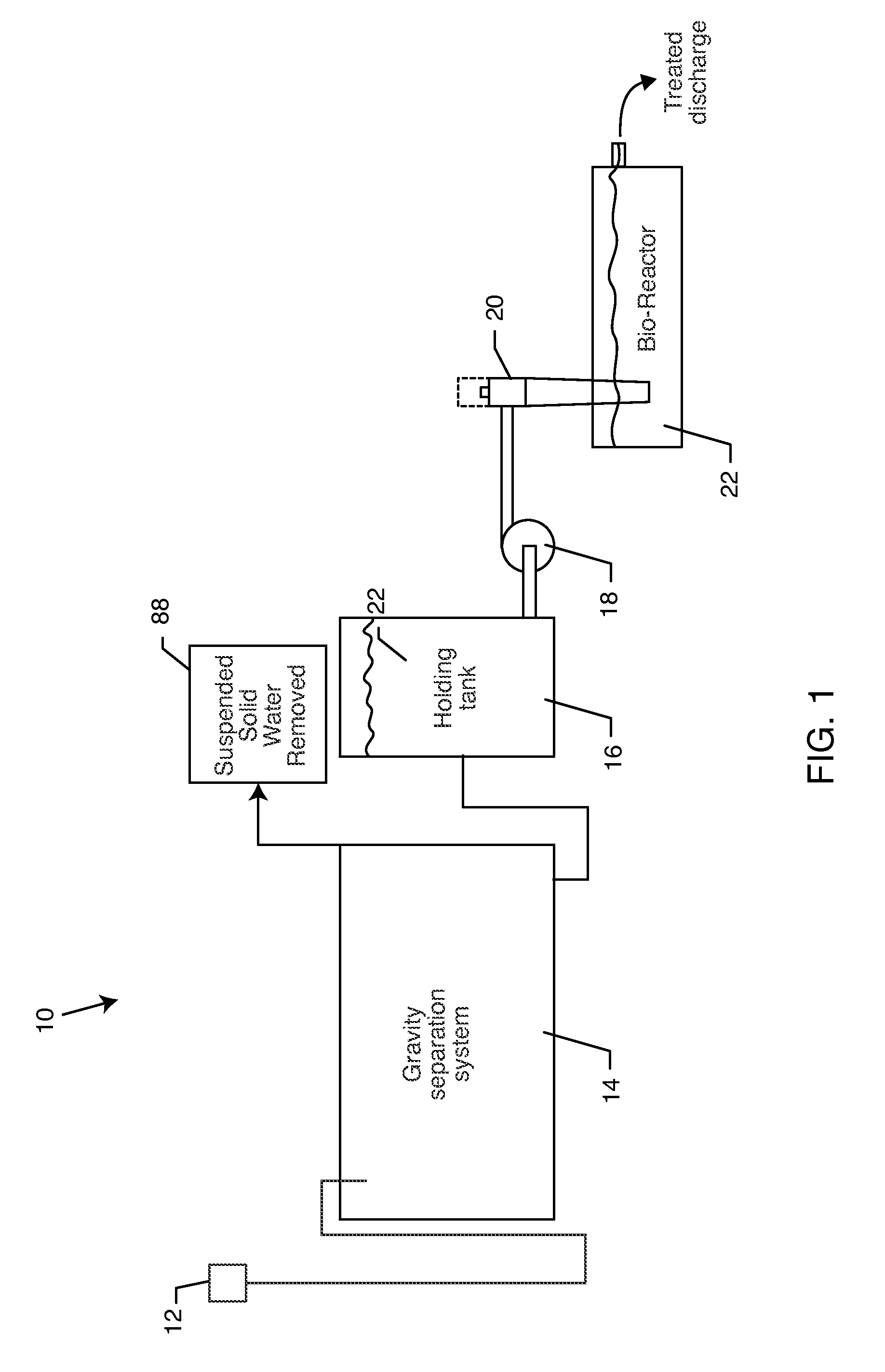
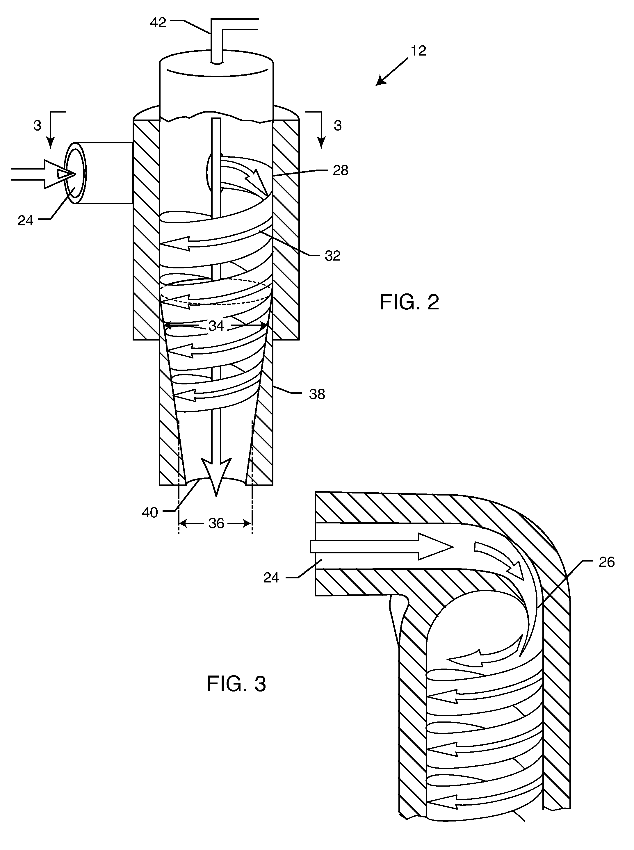
[0027]As shown in the accompanying drawings, for purposes of illustration, the present invention resides in a system for treating wastewater liquid to advantageously utilize aerobic biological species to convert dissolved solids into carbon dioxide and suspended solids. As shown in the exemplary drawings for purposes of illustration, the present disclosure for a wastewater treatment system is referred to generally by the reference numeral 10. Turning now to the representative figures in the specification, FIG. 1 illustrates the wastewater treatment system 10 having a liquid-solid mixer 12 in fluid communication with a floatation tank 14. The floatation tank 14 is a gravity separation system, such as that described in U.S. Pat. No. 6,797,181, the contents of which are herein incorporated by reference. Once the contaminated wastewater, including large particles, fats, grease, and physically emulsified oils and the like are removed from the contaminated wastewater via the floatation ta...


PUM

PropertyMeasurementUnit
diameteraaaaaaaaaa
diameteraaaaaaaaaa
concentrationaaaaaaaaaa

Abstract

A system is disclosed herein for treating wastewater liquid by utilizing aerobic biological species. The contaminated wastewater stream is pretreated in a dissolved air flotation system to remove suspended solid waste, including large particles such as fats, grease, and physically emulsified oils. The purified wastewater containing dissolved waste is thereafter oxygenated and further decontaminated in a bioreactor tank. Biological species in the bioreactor tank consume oxygen and perform bodily functions that converts dissolved waste into easily removable carbon dioxide and suspend solids. Oxygen consumed by the biological species is replenished by pumping the wastewater though a liquid-oxygen mixer. A controller regulates the speed of the pump based on real-time oxygen concentration measurements provided by a corresponding oxygen probe disposed within the wastewater in the bioreactor tank.

Description

BACKGROUND OF THE INVENTION[0001]The present invention generally relates to the treatment of contaminated liquid, such as wastewater. More particularly, the present invention relates to a method for removing contaminants from a liquid by use of a gas replenishment system that controls levels of dissolved oxygen in the liquid. The oxygen contains species capable of converting dissolved solids into carbon dioxide and suspended solids, which are more easily separated from the liquid than dissolved solids. The present invention also pre-treats the wastewater, if needed, to remove large particles, fats, grease, and physically emulsified oils. Membrane separation such as nano filtration or reverse osmosis is also used to remove non-biodegradable organic materials and inorganic ions.[0002]Industrial wastewater contains various pollutants. Such pollutants are present as large particles (larger than one micron), charge stabilized colloidal particles (oil and water emulsions, etc.) and dissol...

Claims


Application Information

Patent Timeline
Patent Type & Authority Applications(United States)
IPC IPC(8): C12M1/04C12M1/08C12M1/09C12M1/36
CPCB01F3/0446C02F3/1294B01F3/12B01F5/0057B01F5/0451B01F5/0659C02F1/008C02F1/24C02F3/26C02F2101/325C02F2209/22C02F2209/40C02F2301/024C02F2301/026C02F2301/066B01F3/0865Y02W10/10B01F23/232B01F23/451B01F23/50B01F25/10B01F25/3131B01F25/435
Inventor MORSE, DWAIN E.
Owner WORLD WATER TECH
Learn More