
Blow Molding Die Assembly, Method of Manufacturing Resin Hollow Body Using the Blow Molding Die Assembly and Resin Hollow Molded Body Manufactured by the Manufacturing Method

Active Publication Date: 2008-02-14
MITSUI CHEM INC
View PDF4 Cites 35 Cited by
  • Summary
  • Abstract
  • Description
  • Claims
  • Application Information

AI Technical Summary

Benefits of technology

[0043]According to the manufacturing method of a resin hollow molded body using the blow molding die assembly according to the present invention, excellent workability can be achieved because a step for closing a hole formed to the resin hollow molded body by welding or fusing becomes unnecessary. Further, since a welded portion or a fused portion for sealing a hole is eliminated, even if gasoline and the like having high permeating property are contained in the hollow molded body, leakage of a gas component can be effectively prevented.
[0044]Further, the hollow molded body obtained with the method of the invention, the automobile fuel tank in particular, is light in weight and suitable for containing fuel having high permeating property such as gasoline and the like.

Problems solved by technology

Accordingly, in the conventional manufacturing method, a step for forming the hole is necessary, from which there has been a problem of increasing man-hours.
However, since parts formed of different materials have no barrier layer between them, there is a problem that a volatile gas such as gasoline and the like passes through the parts.
Even in this case, however, since no barrier layer exists in the portions of the parts welded to the hollow molded body, a gas barrier property cannot be sufficiently provided, from which a problem of gas permeation arises.
In this case, however, a wall thickness of the concave portion gets thinner, then an entire wall thickness must be increased, from which a problem of an increase of weight arises.
However, since EVOH and polyamide are ordinarily inferior to polyolefin in dropping impact resistance, an arrangement having the innermost layer composed of the barrier layer is disadvantageous.
Since fusion bonded portions of the injection molded half-divided bodies must be heated and melted again, energy efficiency is also bad.
However, since a thick parison must be cut off before it is blow molded by the method of the patent document 3, there may be a case that it is difficult to cut off a multilayered passion.
Further, since the parison is blown after it is welded again, a welded portion is not blow extended, and thus wall thickness of the hollow molded body is made uneven.

Method used


Image

  • Blow Molding Die Assembly, Method of Manufacturing Resin Hollow Body Using the Blow Molding Die Assembly and Resin Hollow Molded Body Manufactured by the Manufacturing Method
  • Blow Molding Die Assembly, Method of Manufacturing Resin Hollow Body Using the Blow Molding Die Assembly and Resin Hollow Molded Body Manufactured by the Manufacturing Method
  • Blow Molding Die Assembly, Method of Manufacturing Resin Hollow Body Using the Blow Molding Die Assembly and Resin Hollow Molded Body Manufactured by the Manufacturing Method

Examples


Embodiment Construction

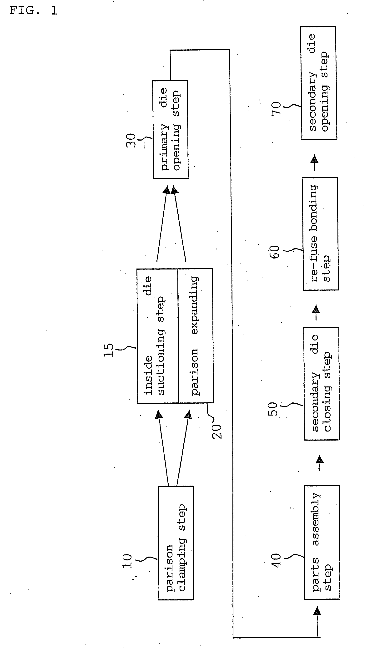
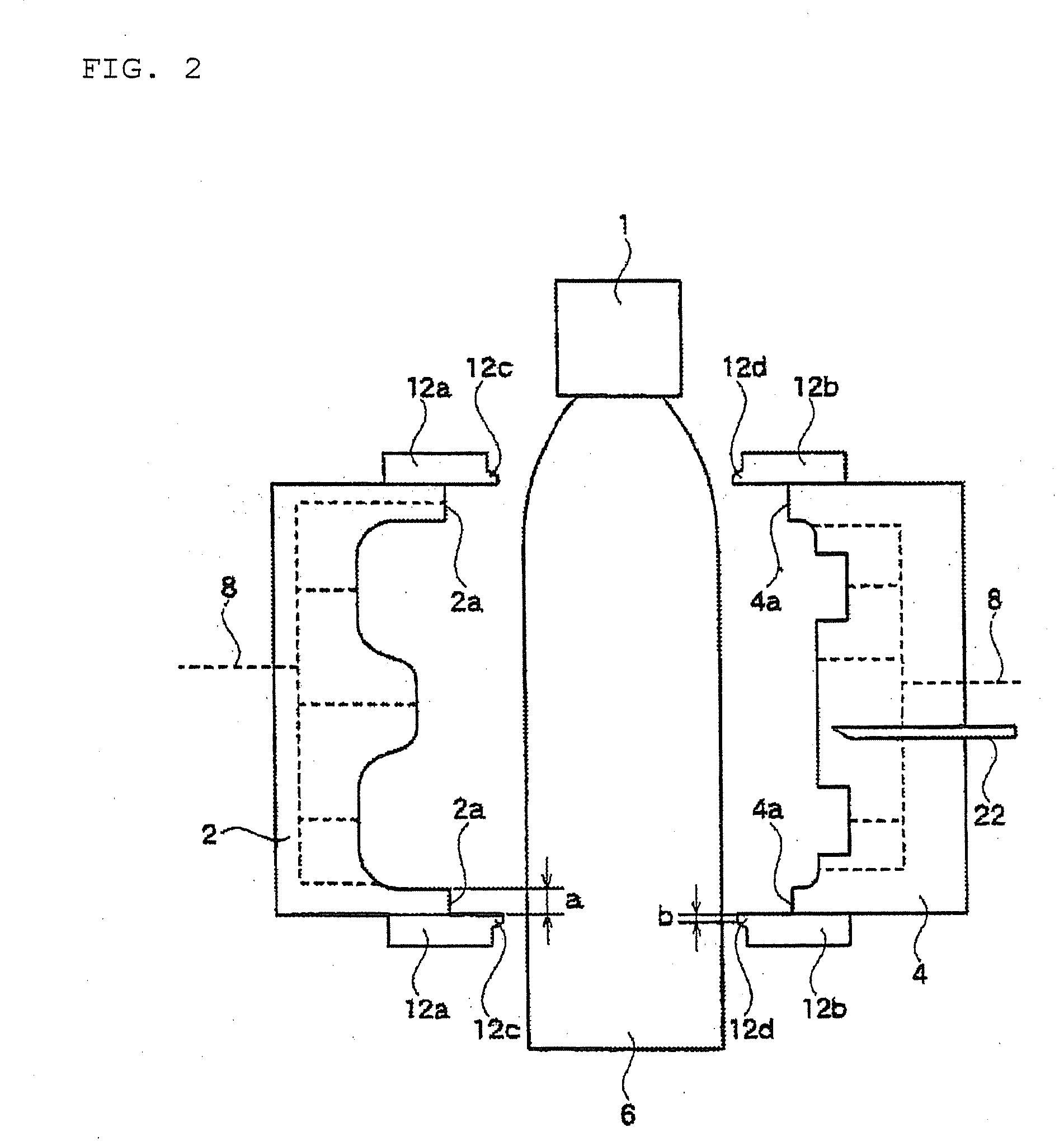
[0065]An embodiment of of the manufacturing method of a resin hollow body according to the present invention will be explained with reference to the figures. FIG. 1 is a block diagram showing steps of the manufacturing method of the resin hollow body according to the present invention. FIG. 2 is a sectional view of dies for embodying the manufacturing method.

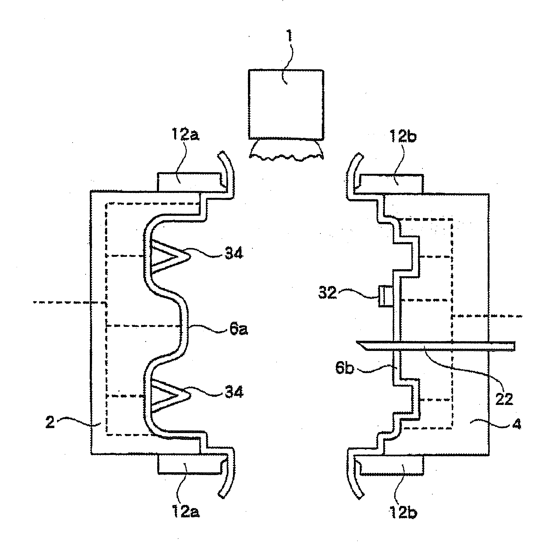
[0066]In the manufacturing method of the resin hollow body according to the present invention, thermoplastic resin such as polyethylene is plasticized by an extruder and a tubular parison is obtained. Thereafter, the parison is inserted into dies before it is not cooled and solidified, and then air is introduced into the parison. Subsequently, the dies are separated once, and after parts are attached to the half-divided parisons (hollow molded bodies) in using a released space of the dies, the dies are abutted again, and a product can be obtained by re-fuse bonding the parisons.

[0067]Note that, in the description, a state of the...


PUM

PropertyMeasurementUnit
Fractionaaaaaaaaaa
Timeaaaaaaaaaa
Widthaaaaaaaaaa

Abstract

To provide a method of manufacturing a resin hollow molded body wherein, predetermined parts can be simply attached when attaching them in the inside of the blow molded hollow body; and the resin hollow molded body, such as a vehicle fuel tank containing a volatile liquid inside thereof, has a good barrier property against a gas component.(Means for Solving the Problem)There is provided a method for obtaining a product of a hollow molded body characterized in that: a thermoplastic resin parison 6, extruded to a tubular state, is expanded by blow molding; then dies 2, 4 are once divided to assemble predetermined parts 32, 34 inside of the hollow molded body; and the surfaces of the divided dies are joined again.

Description

TECHNICAL FIELD [0001]The present invention relates to a blow molding die assembly, a method of manufacturing a resin hollow body using the blow molding die assembly and a hollow molded body manufactured by the manufacturing method, and, in particular, relates to a vehicle fuel tank.BACKGROUND ART [0002]As an automobile fuel tank, there is provided a resin tank in place of a metal tank in response to a request for reduction in weight, and the resin tank can be obtained by hollow blow molding of thermoplastic resin such as polyethylene, etc. In general, a resin material is easily permeated by a volatile component such as gasoline and the like as compared with metal material, a barrier layer with a less permeating property composed of EVOH, nylon or the like is ordinarily disposed to an inner layer and an intermediate layer, and there is proposed a resin tank obtained by multilayer molding with polyolefin and barrier material layers (patent documents 1 and 2).[0003]In general, a fuel ...

Claims


Application Information

Patent Timeline
IPC IPC(8): B29C49/20B29C49/18B29C49/48B29L22/00B65D25/02B29C49/00B29C49/04B60K15/03B65D1/02
CPCB29C49/04Y10T156/1062B29C49/4817B29C2049/2008B29C2791/001B29C2791/006B29L2031/7172B60K15/03177B65D1/02B29C2793/0072B29C49/4273B29C49/4278B29C49/50B29C2049/503B29C2793/00Y10T428/1352Y10T156/1075B29C49/20
Inventor NEMOTO, MIKIO
Owner MITSUI CHEM INC
Learn More