
Pattern forming method and apparatus used for the same

Inactive Publication Date: 2008-02-14
TOKYO ELECTRON LTD
View PDF3 Cites 0 Cited by
  • Summary
  • Abstract
  • Description
  • Claims
  • Application Information

AI Technical Summary

Benefits of technology

[0008]An object of the present invention is to provide a pattern forming method that can prevent a substrate from suffering process faults generated thereon. Another object of the present invention is to provide an apparatus used for the pattern forming method and a computer readable storage medium that stores a control program for executing the pattern forming method.

Problems solved by technology

Consequently, in cleaning performed before the immersion light exposure, the resist film may suffer process faults, such as bubbles and liquid residues, generated during the immersion light exposure due to the residual part of the cleaning liquid.
Further, in cleaning performed after the immersion light exposure, process faults, such as lack of process uniformity, may be caused.

Method used


Image

  • Pattern forming method and apparatus used for the same
  • Pattern forming method and apparatus used for the same
  • Pattern forming method and apparatus used for the same

Examples


Embodiment Construction

[0023]An embodiment of the present invention will now be described with reference to the accompanying drawings. In the following description, the constituent elements having substantially the same function and arrangement are denoted by the same reference numerals, and a repetitive description will be made only when necessary.

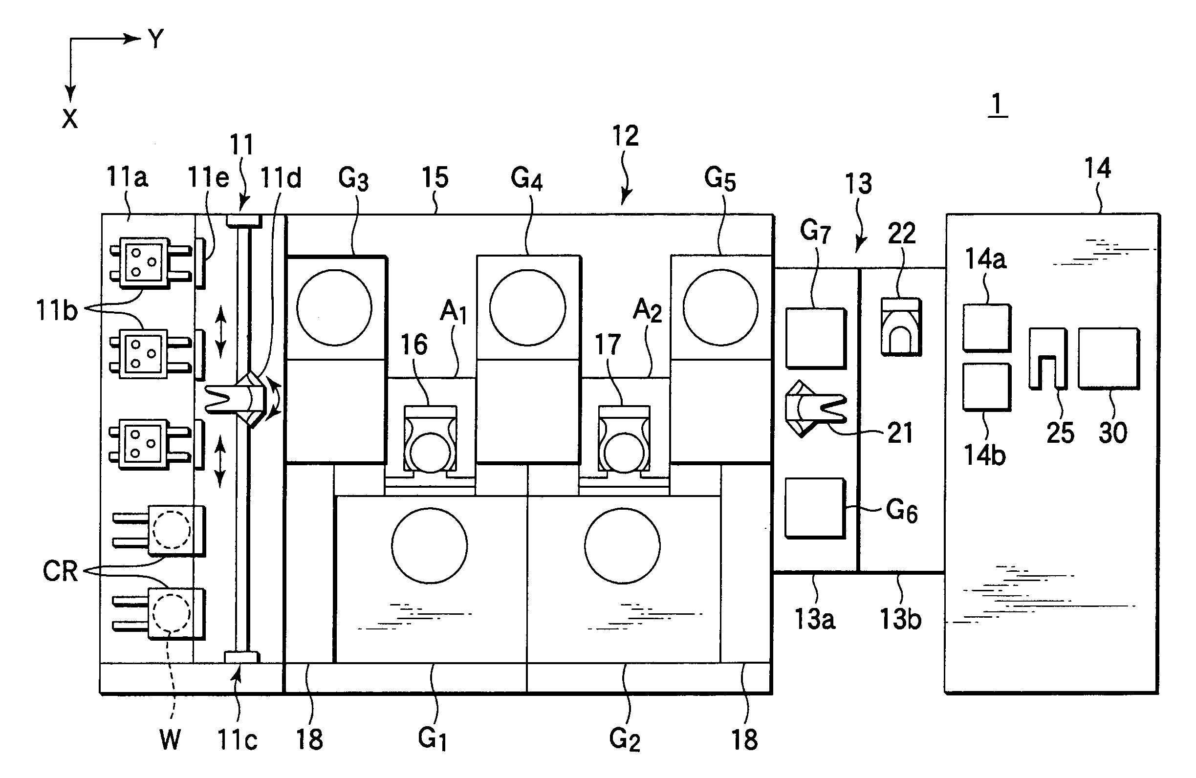
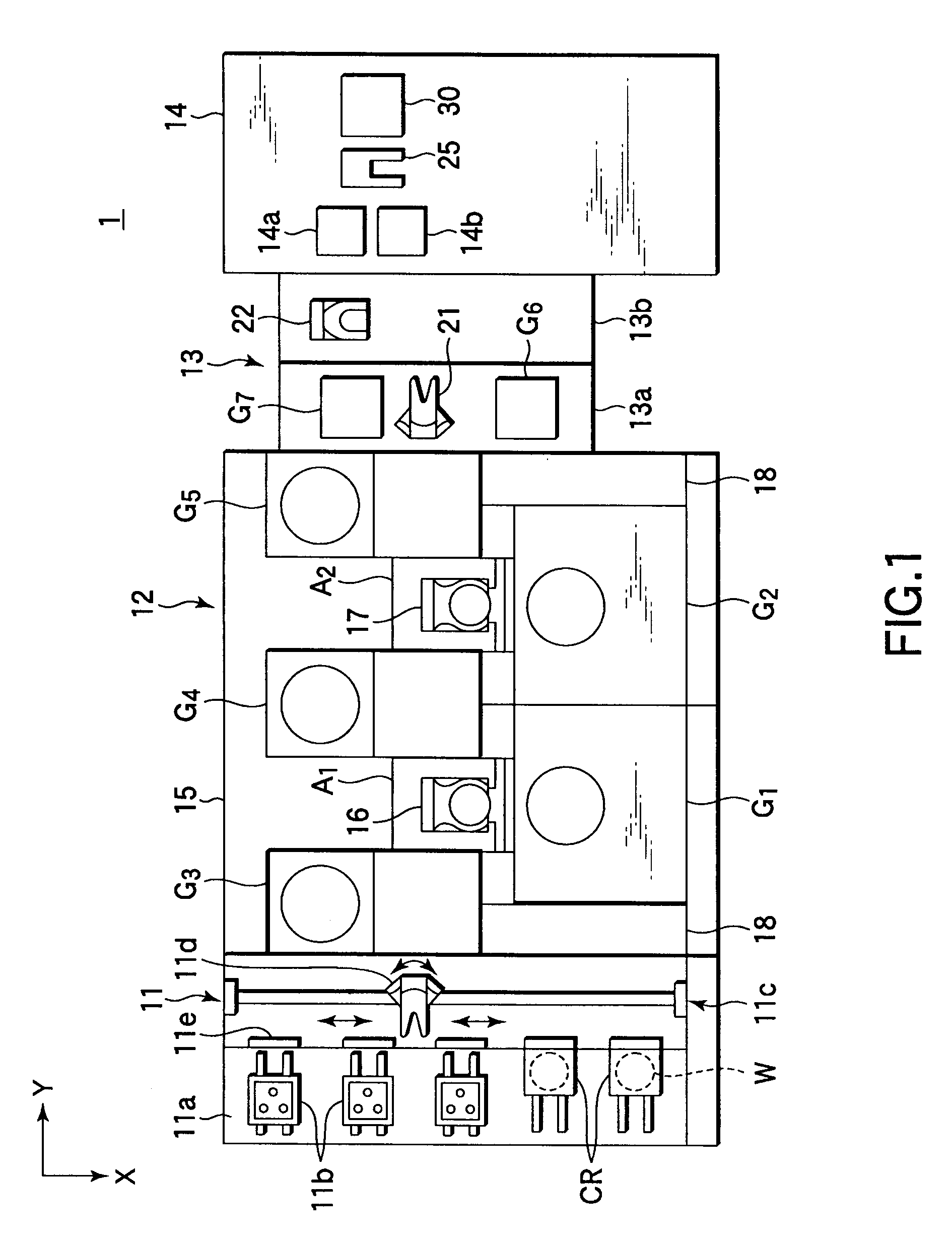
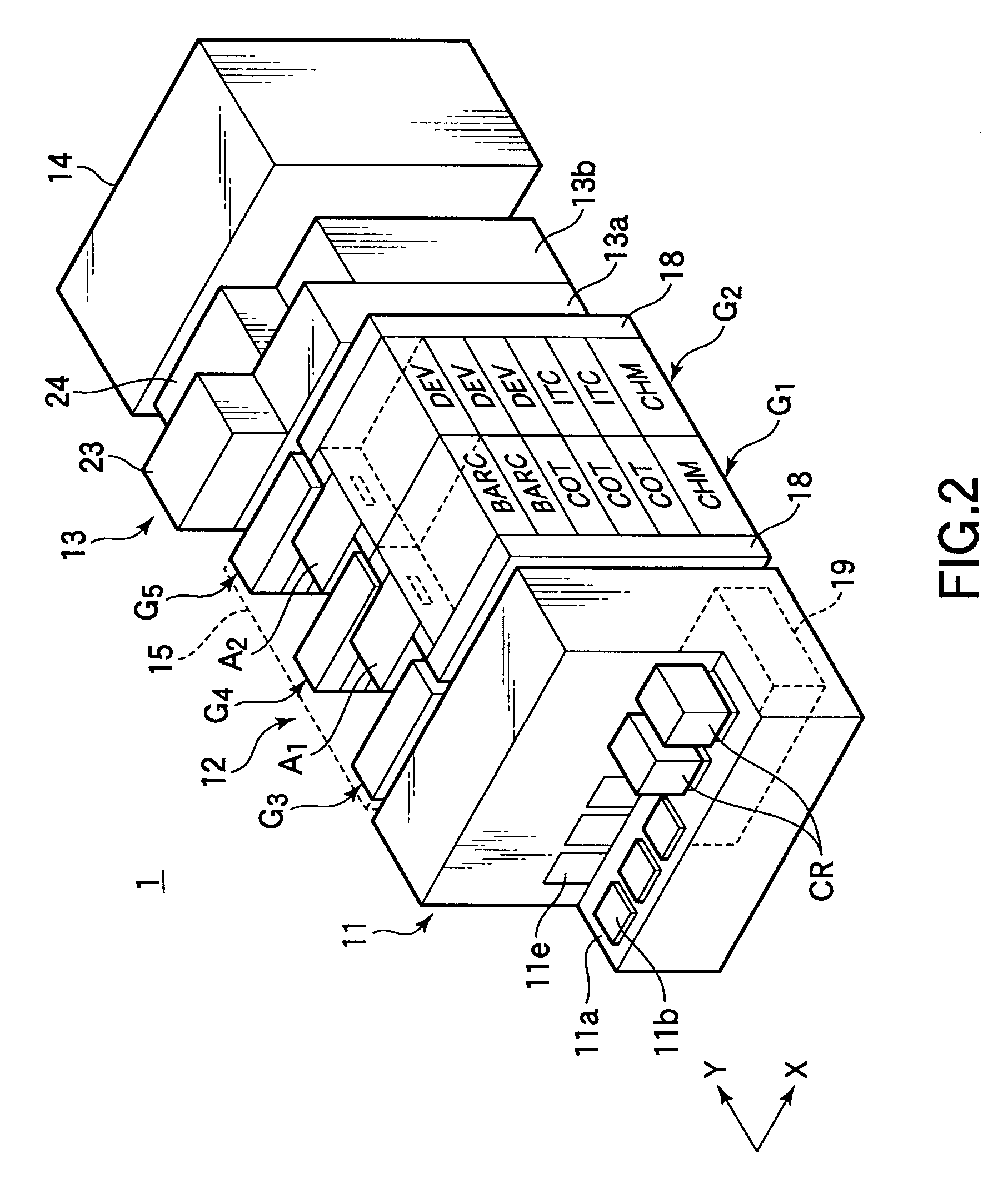
[0024]FIG. 1 is a plan view schematically showing the layout of a pattern forming apparatus according to an embodiment of the present invention. FIG. 2 is a perspective view schematically showing the pattern forming apparatus. The pattern forming apparatus 1 is designed to form a predetermined resist pattern on a semiconductor substrate or wafer W. This pattern forming apparatus 1 includes a cassette station 11 used as a transfer station for wafers W, a process station 12 comprising a plurality of processing units each for performing a predetermined process on a wafer W, a light exposure apparatus 14 for performing a light exposure process on a wafer W, and an ...


PUM


Abstract

A pattern forming method includes performing resist coating on a substrate, thereby forming a resist film; performing immersion light exposure in accordance with a predetermined pattern on the resist film formed on the substrate, while immersing the resist film in a high refractive index liquid having a refractive index higher than water; and performing development of the resist film after the immersion light exposure. Further, this method includes performing cleaning on the substrate by use of a cleaning liquid containing the same active ingredient as the high refractive index liquid in at least one of a first period after formation of the resist film and before the immersion light exposure and a second period after the immersion light exposure and before the development.

Description

BACKGROUND OF THE INVENTION[0001]1. Field of the Invention[0002]The present invention relates to a pattern forming method and an apparatus used for the method, wherein the method includes an immersion light exposure process arranged to subject a resist film formed on a substrate to light exposure in accordance with a predetermined pattern while immersing the resist film in a high refractive index liquid.[0003]2. Description of the Related Art[0004]In the process of manufacturing semiconductor devices, photolithography techniques are used for forming circuit patterns on semiconductor wafers. Where a circuit pattern is formed by use of photolithography, the process steps are performed, as follows. Specifically, a resist liquid is first applied to a semiconductor wafer to form a resist film. Then, the resist film is irradiated with light to perform light exposure on the resist film in accordance with the circuit pattern. Then, the resist film is subjected to a developing process.[0005]...

Claims


Application Information

Patent Timeline
IPC IPC(8): G03B27/42G03C5/04
CPCG03F7/70925G03F7/70341G03F7/2041H01L21/0274
Inventor YAMAMOTO, TARO
Owner TOKYO ELECTRON LTD
Learn More