
Combustion apparatus

a combustion apparatus and combustion chamber technology, applied in lighting and heating apparatus, domestic stoves or ranges, heating types, etc., can solve the problems of inability to complete combustion, inability to fully burn wood, and inability to emit combustion gases and particulates, etc., to achieve clean, smokeless burning, and high heat energy. , the effect of easy operation

Inactive Publication Date: 2008-02-14
FEDERICO DOMINIC J
View PDF27 Cites 11 Cited by
  • Summary
  • Abstract
  • Description
  • Claims
  • Application Information

AI Technical Summary

Benefits of technology

[0017]The apparatus employs initial combustion and gasification of solid fuel in a primary combustion chamber and a secondary combustion in a secondary combustion chamber. Measured amounts and distribution of pre-heated primary and secondary combustion air is provided via an oxygen introduction mechanism and a pressurizing mechanism, resulting in a controlled, self-sustaining continuous blue flame secondary combustion in the secondary combustion chamber. The resulting superheated exhaust gases have extremely low particulate emissions and a very limited amount of granular ash is produced.
[0021]A combination of high temperatures and an extended transit time of the combustion gases from the primary combustion chamber to the secondary combustion chamber, together with measured amounts of supplemental oxygen in the secondary combustion chamber, allow for virtually complete combustion of the solid fuel, yielding an extremely clean, smokeless burn. The extended transit time is provided by the depth and density of the char fuel bed and the gas flow resistance of the divider between the primary and secondary combustion chambers. A limit on the absolute air flow into the primary and secondary combustion chambers also controls the overall combustion rate and the transit time of the combustion gases. The rate of fuel combustion is substantially constant, dictated by the fixed amount of combustion airflow and the ratio of primary and secondary combustion airflows.
[0022]The combustion chambers and divider are constructed at least in part of a durable material having the properties of absorbing and retaining high levels of heat energy. This allows the combustion apparatus to be thermostatically controlled. By controlling the amounts of combustion air allowed into the combustion chambers, combustion can be initiated and halted. When the supply of combustion air is discontinued, combustion of the solid fuel ceases completely. However, the heat energy absorbed by the material comprising the combustion chambers and divider maintains the internal temperature of the combustion chambers well above the flash point temperature of the solid fuel for an extended period of time. Upon the reintroduction of combustion air into the super-heated combustion chambers the solid fuel and combustion gases automatically re-ignite and combustion continues. The introduction and discontinuation of combustion air into the combustion chambers may be controlled by a thermostat, thus allowing the combustion apparatus to maintain an ease of operability similar to oil or gas fueled furnaces and boilers.
[0023]The present invention also employs several design features to improve the safety of its operation. A typical danger with wood fired heating systems is the uncontrolled provision of heat to a heat exchanger. If too much heat is provided to a heat exchanger, for example during a power failure whereby the heat exchange medium within the heat exchanger (typically a liquid) stops circulating, the heat exchanger may overheat and the heat exchange medium contained therein may pressurize beyond the capability of the heat exchanger to contain it, causing a rupture of the system and a potential danger to any bystanders. The present invention minimizes the potential of overheating the heat exchanger by setting the default state of the apparatus to prevent introduction of combustion air into the combustion chambers. Thus, if there is a power interruption, the apparatus is designed to automatically cut off combustion air from the combustion chambers, causing further combustion to cease. As no further heat energy is added into the system, the heat exchanger does not receive additional heat energy and further dangerous pressurization of the heat exchange medium does not occur. Another design feature requires the heated exhaust gases to travel at least in part in a downward direction from the combustion chambers to the heat exchanger. Upon a power failure, the apparatus will cease providing the forces necessary to move the exhaust gases downward, so the hot gases will naturally rise and thus be prevented from reaching the heat exchanger. An additional feature of the present invention is a direct communication between the primary combustion chamber and the exhaust structure, controlled by a bypass damper. The bypass damper is designed to be opened when the access door to the primary combustion chamber is opened and to be closed when the access door to the primary combustion chamber is closed, thereby automatically releasing hot combustion gases out of the combustion chambers when a user accesses the primary combustion chamber, preventing a flash ignition in the primary combustion chamber. These safety features represent improvements over the known art in the safe operation of the apparatus.

Problems solved by technology

At those temperatures, however, complete combustion is not possible, resulting in emissions of combustion gases and particulates, often in the form of visible smoke.
These emissions are considered pollutants and are undesirable.
However, solid fuel combustion apparatuses intended for use in residential or light commercial settings known in the art cannot achieve consistent continuous blue flame burns.
Known solid fuel combustion apparatuses are also typically difficult to control, in that they need direct user attention to begin combustion, to monitor combustion, to end combustion, and to re-start combustion.
This does not lend itself to thermostatic control, whereby the generation of heat is called for by an automatic device, such as a thermostat, in response to environmental conditions.
Those devices that do employ thermostatic control typically do so with poor emissions and efficiency characteristics.
Known solid fuel combustion apparatuses are also typically less safe than other heating systems, due to the difficult to control combustion.
This may lead to dangerous overheating with deleterious effect on any heating system to which the apparatus is connected.
The resulting superheated exhaust gases have extremely low particulate emissions and a very limited amount of granular ash is produced.
However, the heat energy absorbed by the material comprising the combustion chambers and divider maintains the internal temperature of the combustion chambers well above the flash point temperature of the solid fuel for an extended period of time.
A typical danger with wood fired heating systems is the uncontrolled provision of heat to a heat exchanger.
If too much heat is provided to a heat exchanger, for example during a power failure whereby the heat exchange medium within the heat exchanger (typically a liquid) stops circulating, the heat exchanger may overheat and the heat exchange medium contained therein may pressurize beyond the capability of the heat exchanger to contain it, causing a rupture of the system and a potential danger to any bystanders.
Thus, if there is a power interruption, the apparatus is designed to automatically cut off combustion air from the combustion chambers, causing further combustion to cease.

Method used


Image

  • Combustion apparatus
  • Combustion apparatus
  • Combustion apparatus

Examples


Embodiment Construction

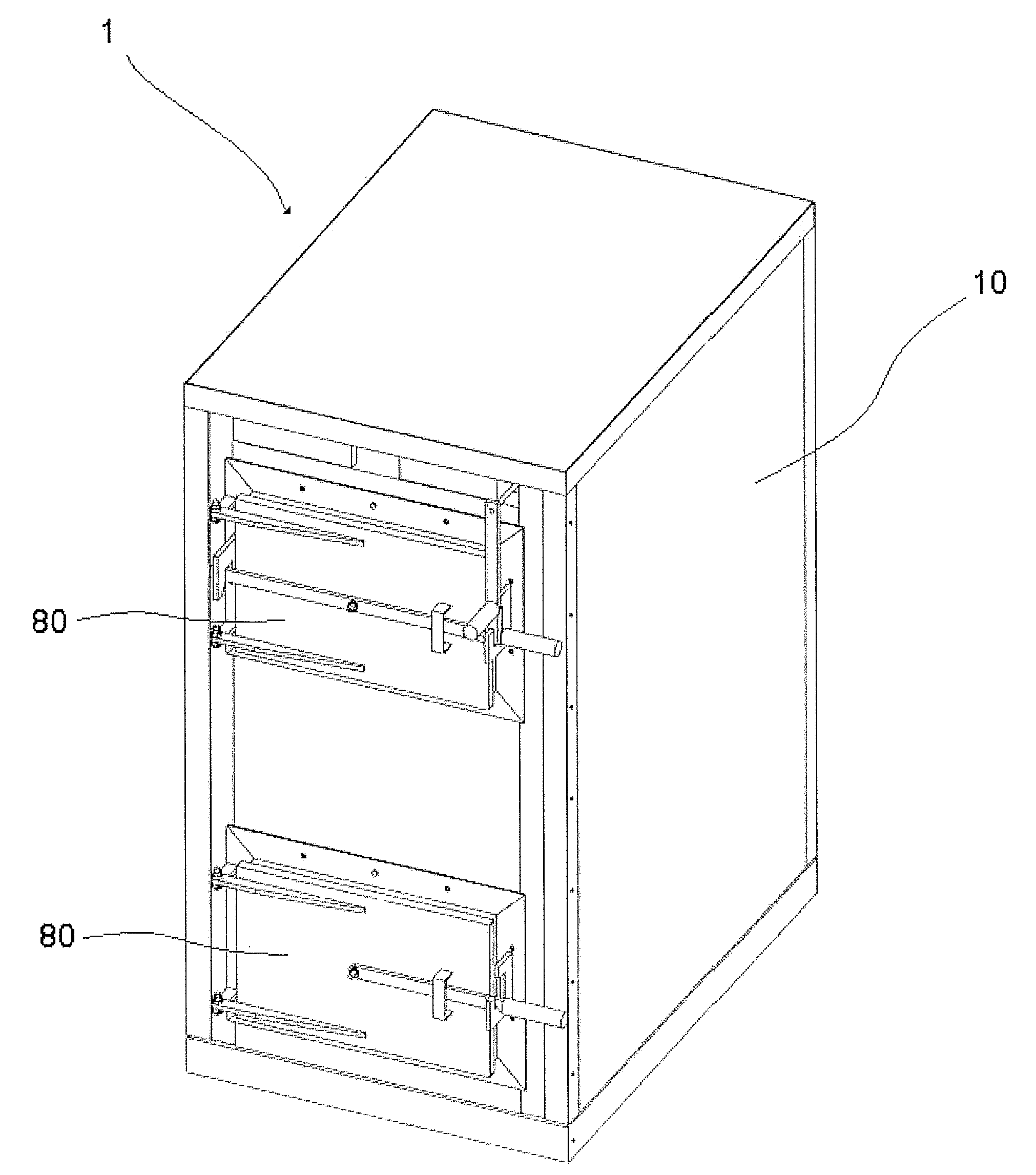
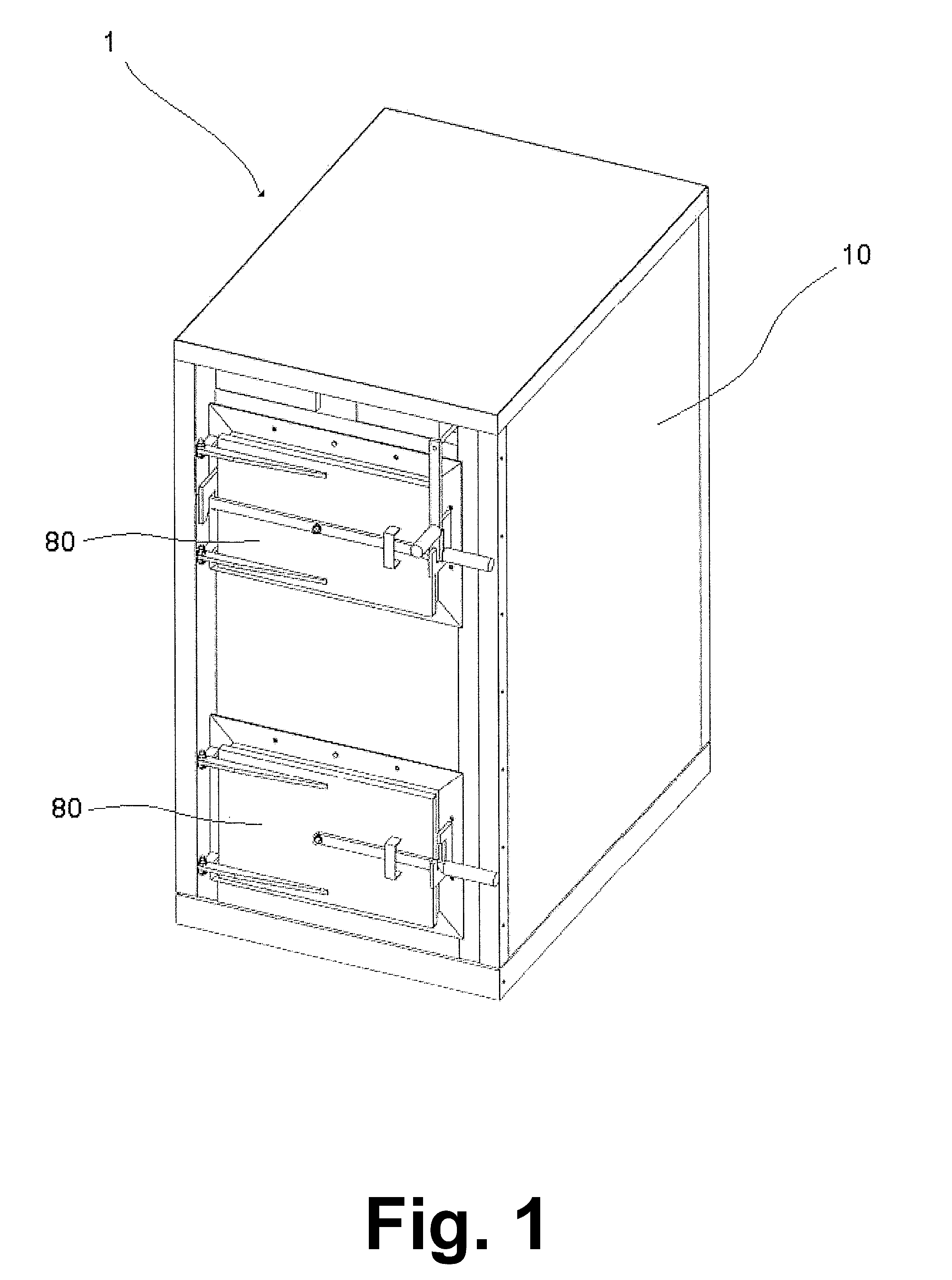
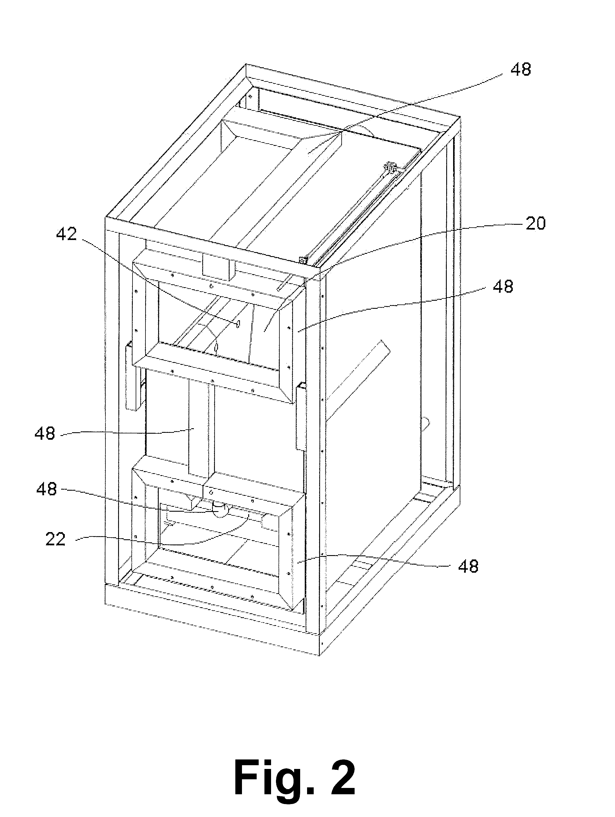
[0035]The combustion apparatus 1 of the present invention is comprised of an insulated housing 10, a primary combustion chamber 20, a secondary combustion chamber 22, a divider 30 disposed between and separating the primary and secondary combustion chambers 20,22, an oxygen introduction mechanism 40, a pressurizing mechanism 50, and an exhaust structure 60.

[0036]The housing 10 of the present invention is constructed of a heavy-duty metallic material, such as steel or cast iron, though other materials may also be used. It comprises insulation within its interior sufficient to allow for safe contact of the outer surface during operation of the combustion apparatus 1. The housing 10 defines an internal space in which the other elements are located, though portions of the pressurizing mechanism 50 and the exhaust structure 60 extend outside the housing 10. See FIGS. 1, 5, 8, 9, and 10. One or more access doors 80 may be provided to allow access into the interior of the housing 10. See F...


PUM


Abstract

An improved solid fuel combustion apparatus intended for use in residential or light commercial settings capable of sustaining a controlled, continuous blue flame burn, resulting in high efficiency heat output with low emissions and low ash. The combustion apparatus is further capable of being thermostatically controlled, turning off combustion of the fuel when a desired temperature is reached and automatically re-igniting when more heat is called for, and also comprises improved safety features.

Description

BACKGROUND OF THE INVENTION[0001]1. Technical Field[0002]The invention relates generally to devices suitable for burning solid fuel for heat and more particularly to wood burning combustion apparatuses intended for use in residential or light commercial settings. Such combustion apparatuses include wood stoves, wood fired boilers, and the like.[0003]2. Description of Prior Art[0004]Solid fuel burning combustion apparatuses are well-known in the art. Common examples include wood stoves and wood fired boilers. All such apparatuses operate on the following basic principles: solid fuel and combustion air (comprising oxygen) are ignited; some degree of gasification of the solid fuel occurs, resulting in the release of gases which mix with the combustion air to achieve further combustion; and the output of the combustion process is heat, unburned combustion gases, and particulates. Devices to achieve combustion of solid fuel may comprise one or more chambers in which the combustion occurs...

Claims


Application Information

Patent Timeline
Patent Type & Authority Applications(United States)
IPC IPC(8): F24C1/14
CPCF24B1/026F24B9/04F24B5/023
Inventor FEDERICO, DOMINIC J.
Owner FEDERICO DOMINIC J
Learn More