
Aluminum reduction cell fuse technology

a technology of reduction cell and fuse, which is applied in the field of aluminum reduction cell fuse technology, manufacturing of aluminium, and can solve the problems of loss of production time, damage to the plant, and limitations of the prior ar

Inactive Publication Date: 2008-02-07
BHARAT ALUMINUM
View PDF3 Cites 11 Cited by
  • Summary
  • Abstract
  • Description
  • Claims
  • Application Information

AI Technical Summary

Benefits of technology

[0023] A method of taking inoperative pot online using fuse in an aluminium manufacturing plant operating on electrolysis process is disclosed. The manufacturing plant comprises of plurality of electrolysis cells or pots connected in series. Some of the pots are kept off line during start up of the plant by shorting the risers of the non running pots to the cathode bus bar (31) by shorted joints (II). The method comprises, connecting fuse assemblies in parallel with the shorted joints; inserting insulating insert plates between ...

Problems solved by technology

This step rise is required as a sudden increase in the current will increase the voltage across the individual pot which can affect or even cause damage to the plant.
In addition to loss of production time, there are other disadvantages and / or limitations of the prior art.
For example, disturbances to the running operating pots due to reduction of current to zero and again increasing to full value also are disadvantageous.
There is also an adverse impact on the power plant operation as well as on its equipment and production losses may be experienced due to a decrease in line amperage during power on of pots, as well as production time lost in this process.

Method used


Image

  • Aluminum reduction cell fuse technology
  • Aluminum reduction cell fuse technology
  • Aluminum reduction cell fuse technology

Examples


Embodiment Construction

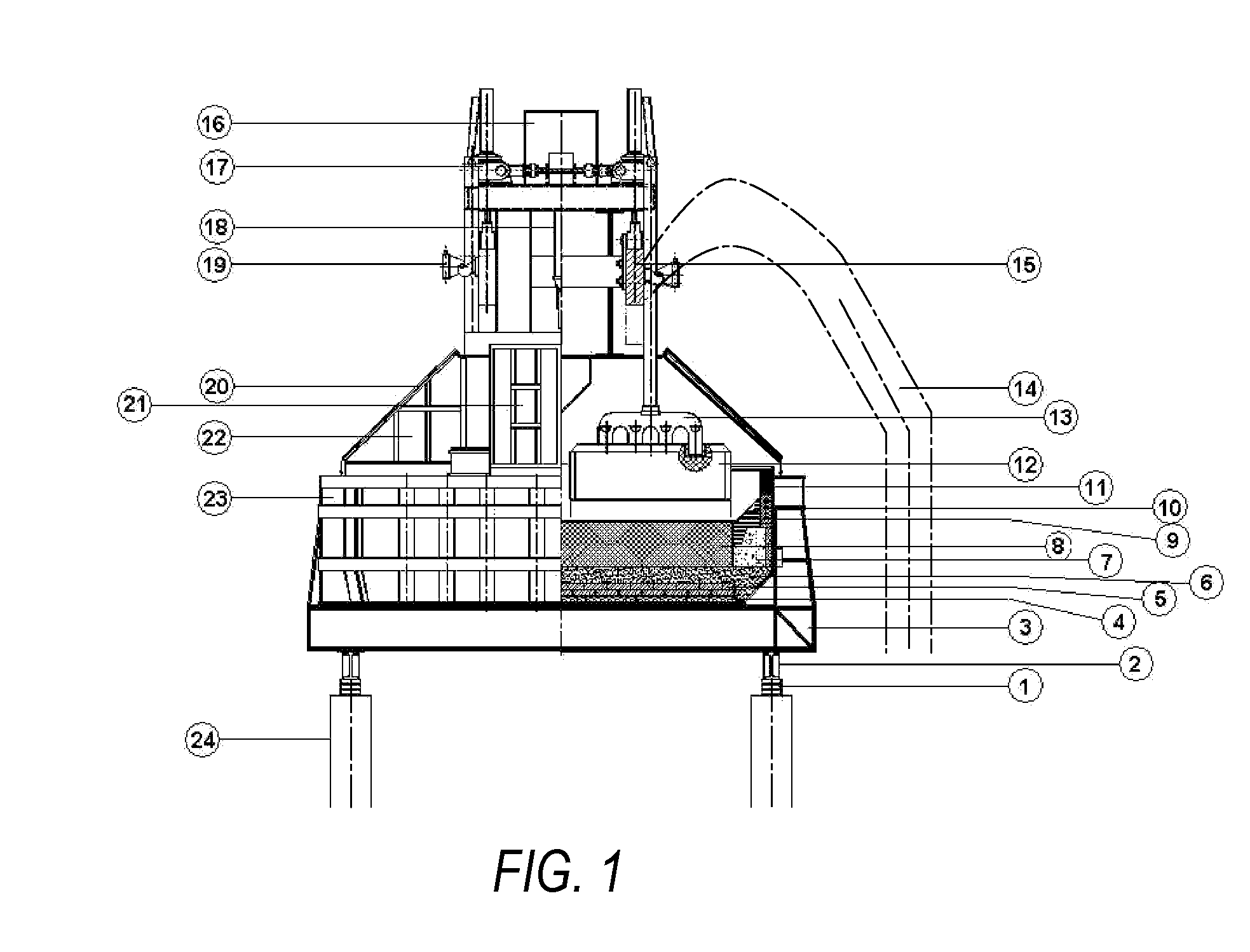
[0034] The problems and shortcomings associated with prior art techniques and approaches are overcome by the present disclosure as described below in an preferred embodiment. However, it is understood that the embodiment is illustrated in the accompanying drawings, through out which like reference letters indicate corresponding parts in the various figures.

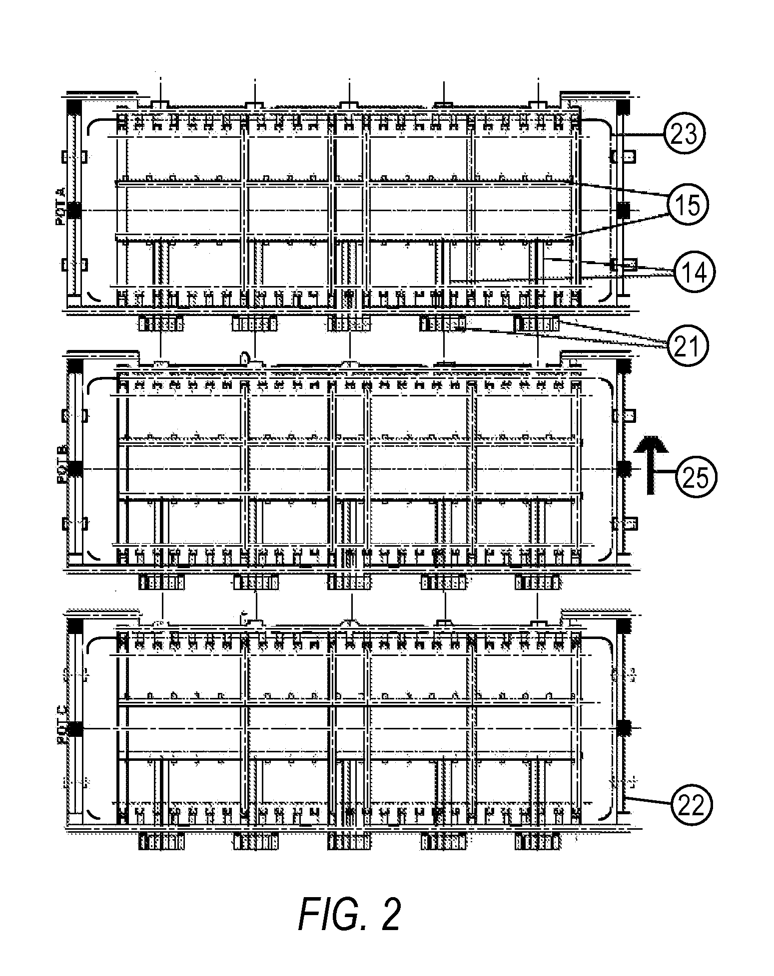
[0035] When the manufacturing process is started, the condition of the three representative pots (e.g., Pot A, Pot B and Pot C) are shown in FIG. 3.

[0036] Out of these three pots, Pot A and Pot C are running pots and Pot B is a non running pot when the manufacturing process is started. In the case of Pot A and Pot C, the shorted joints (II) are kept in an open condition by inserting the insulating insert plates (33) between the short circuit bus bars (21) and risers (14). Thus, the current in the risers (14) of these pots is fed to the anode assemblies (13) and passed through the carbon anode blocks (12) for electrolysis as show...


PUM

PropertyMeasurementUnit
Fractionaaaaaaaaaa
Fractionaaaaaaaaaa
Fractionaaaaaaaaaa

Abstract

A method of taking inoperative pot online using fuse in an aluminium manufacturing plant operating on electrolysis process is disclosed. The manufacturing plant comprises of plurality of electrolysis cells or pots connected in series. Some of the pots are kept off line during start up of the plant by shorting the risers of the non running pots to the cathode bus bar (31) by shorted joints (11). The method comprises, connecting fuse assemblies in parallel with the shorted joints; inserting insulating insert plates between the risers and the short circuit bus bars and securing the insulating insert plates to isolate the short circuit bus bars from the risers (14) such that the total rated current passes through the fuse assemblies. The fuse elements in the fuse assemblies melt within about 8 to 10 minutes, completely isolating the short circuit bus bars from the risers such that the risers now feed the current to the anode assemblies of the non running pot. Feeding of charge to the non running pot is the started, thus taking the non running pot on line.

Description

CROSS-REFERENCE TO RELATED APPLICATIONS [0001] This application claims priority from Indian Patent Application Serial No. 1102 / MUM / 2006 filed Jul. 11, 2006, the disclosure of which, including the specification, drawings and claims, is incorporated herein by reference in its entirety. FIELD OF INVENTION [0002] The present disclosure relates generally to manufacturing metals from their intermediate compounds or ores by an electrolysis process. More particularly, the present disclosure relates to manufacturing of aluminium from intermediate compounds such as, for example, alumina. BACKGROUND [0003] Aluminium has many useful properties. Accordingly, it is second in production, after iron and steel. Because the density of aluminium is low, it is used for forming many strong alloys that contain relatively small percentages of silicon, copper, manganese, magnesium, and zinc. These alloys, with their light weight and high strength, are preferred for use in many industries like automotive, c...

Claims


Application Information

Patent Timeline
IPC IPC(8): C25D3/66
CPCC25C3/20C25C3/16
Inventor RAMASWAMY, J.DIVAKARAN, P.
Owner BHARAT ALUMINUM
Learn More