
Electrolytes, cells and methods of forming passivaton layers

a technology of passivaton and electrolyte, which is applied in the direction of non-aqueous electrolyte cells, cell components, sustainable manufacturing/processing, etc., can solve the problem of significant irreversible capacity loss, and achieve the effect of improving the thermal stability of lithium

Inactive Publication Date: 2008-01-31
AIR PROD & CHEM INC
View PDF41 Cites 123 Cited by
  • Summary
  • Abstract
  • Description
  • Claims
  • Application Information

AI Technical Summary

Benefits of technology

The invention provides an electrolyte for lithium secondary batteries that has a suitable SEI layer and improved thermal stability compared to conventional electrolytes. The electrolyte also has better high temperature charge / discharge cycling stability than conventional electrolytes. The electrolyte can contain additives such as chelato-borate salts or lithium difluorooxalatoborate. The invention also provides cells comprising the electrodes and the electrolyte. The technical effects of the invention are improved performance and stability of lithium secondary batteries.

Problems solved by technology

Use of ethylene carbonate as one of the cosolvents leads to stable passivation layers, while using high levels of propylene carbonate in the absence of ethylene carbonate leads to significant irreversible capacity loss due to exfoliation of the graphite.
A key challenge to the reversibility of cells has been the reactivity of the electrolyte solution components (salt and solvent); especially under the charging conditions.

Method used


Image

  • Electrolytes, cells and methods of forming passivaton layers
  • Electrolytes, cells and methods of forming passivaton layers
  • Electrolytes, cells and methods of forming passivaton layers

Examples


control example 1a

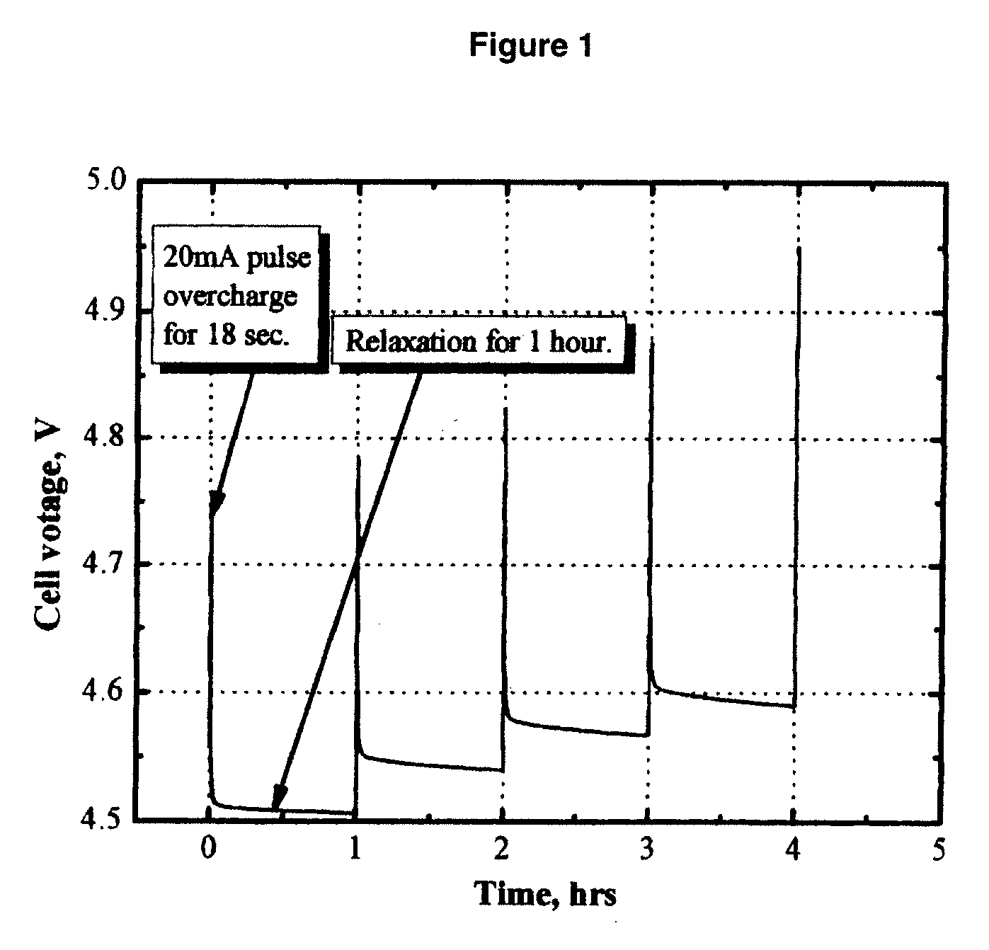
[0062]FIG. 1 shows the cell voltage of a MCMB / Li1.1[Mn1 / 3Ni1 / 3Co1 / 3]0.9O2 (L333) lithium-ion cell that was pulse-overcharged. The electrolyte used was 1.2 M LiPF6 in EC / PC / DMC (1:1:3 by weight, EC stands for ethylene carbonate, PC stands for propylene carbonate, and DMC stands for dimethyl carbonate.). The cell was pulse-overcharged at an 8 C rate (20 mA) for 18 seconds every 60 minutes. FIG. 1 clearly shows that the cell voltage steadily increased with the number of pulse current applied. Only in 4 pulses, the peak voltage of the cell increased to 4.95 V, which is high enough to trigger the decomposition of the positive electrode and the non-aqueous electrolytes.

control example 1b

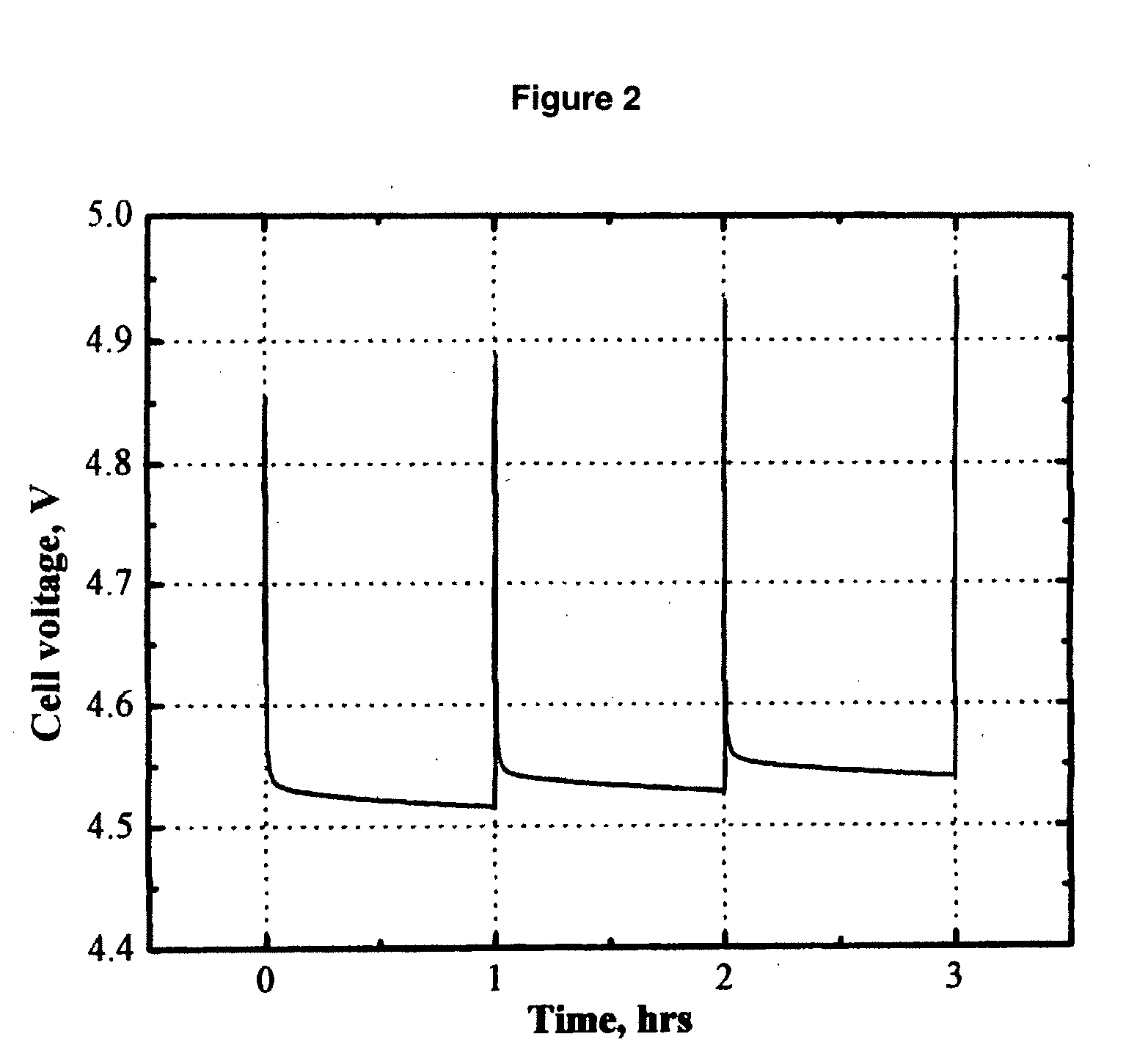
[0063]FIG. 2 shows the cell voltage of a MCMB / Li1.1[Mn1 / 3Ni1 / 3Co1 / 3]0.9O2 (L333) lithium-ion cell that was pulse-overcharged. The electrolyte used was 0.8 M LiBOB in EC / PC / DMC (1:1:3 by weight). The cell was pulse-overcharged at an 8 C rate (20 mA) for 18 seconds every 60 minutes. FIG. 2 clearly shows that the cell voltage steadily increased with the number of pulse current applied. Only in 4 pulses, the peak voltage of the cell increased to 4.95 V, which is high enough to trigger the decomposition of the positive electrode and the non-aqueous electrolytes.

control example 1c

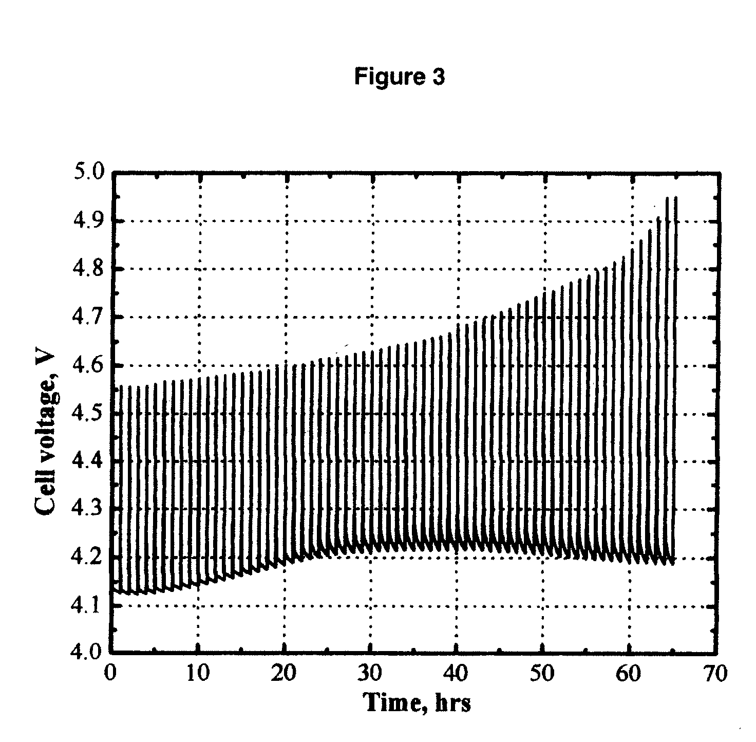
[0064]FIG. 3 shows the cell voltage of a MCMB / Li1.1[Mn1 / 3Ni1 / 3Co1 / 3]0.9O2 (L333) lithium-ion cell that was pulse-overcharged. The electrolyte used was 0.4 M Li2B12F9H3 (AP-F9) in EC / PC / DMC (1:1:3 by weight). The cell was pulse-overcharged at an 8 C rate (20 mA) for 18 seconds every 60 minutes. FIG. 3 clearly shows that the salt AP-F9 has the redox shuttle capability to carry charge through the lithium-ion cell and hence improve the pulse overcharge tolerance of the cell.


PUM

PropertyMeasurementUnit
temperatureaaaaaaaaaa
voltageaaaaaaaaaa
temperaturesaaaaaaaaaa

Abstract

An electrolyte comprising at least one organic aprotic solvent, at least one salt and at least one chelatoborate additive. A method of forming an SEI layer in a cell comprising a positive electrode, a negative electrode and an electrolyte, said method comprising the step of overcharging the electrolyte prior to fabricating the cell, or said cell during the formation cycle.

Description

[0001] This Application is a continuation in part of application Ser. No. 11 / 300,287, filed on Dec. 15, 2005. application Ser. No. 11 / 300,287 claims the benefit of Provisional Application No. 60 / 642,815, filed Jan. 11, 2005. The disclosure of foregoing applications is hereby incorporated by reference.STATEMENT REGARDING FEDERALLY SPONSORED RESEARCH OR DEVELOPMENT [0002] The Government has rights in this invention pursuant to Agreement 85N14 between the Argonne National Laboratory and Air Products And Chemicals, Inc.BACKGROUND OF THE INVENTION [0003] Lithium and Lithium-ion secondary batteries, by virtue of the large reduction potential and low molecular weight of elemental lithium, offer a dramatic improvement in power density over existing primary and secondary battery technologies. Lithium secondary batteries are batteries containing metallic lithium as the negative electrode. Lithium ion secondary batteries contain a lithium ion host material as the negative electrode. By “second...

Claims


Application Information

Patent Timeline
Patent Type & Authority Applications(United States)
IPC IPC(8): H01M6/16H01G11/06H01G11/54H01G11/58H01G11/60H01G11/62H01M4/131H01M4/133H01M4/38H01M4/485H01M4/505H01M4/525H01M4/58H01M4/587H01M10/052H01M10/0525H01M10/0567H01M10/0568H01M10/0569H01M10/36
CPCH01M4/131H01M4/133Y02E60/122H01M10/0567H01M10/0568H01M10/052Y02E60/10Y02P70/50H01M10/05H01M4/02H01M4/48H01M4/58
Inventor CHEN, ZONGHAIAMINE, KHALIL
Owner AIR PROD & CHEM INC
Learn More