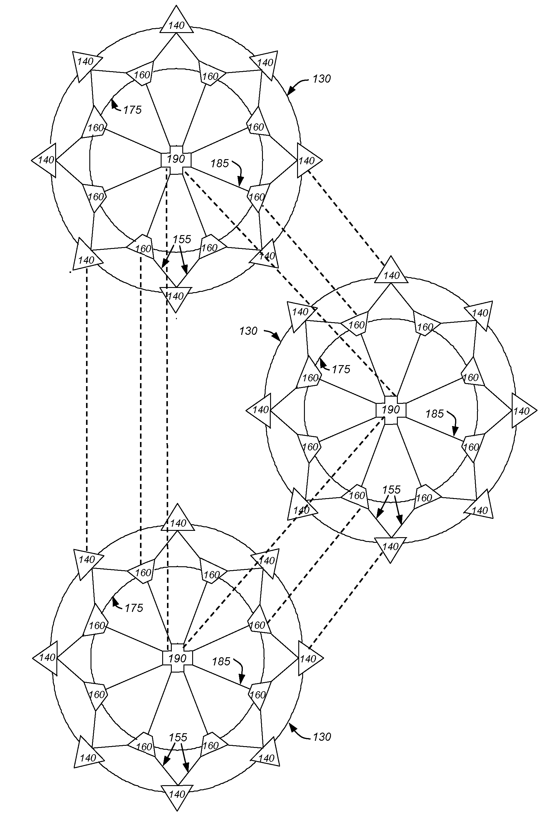
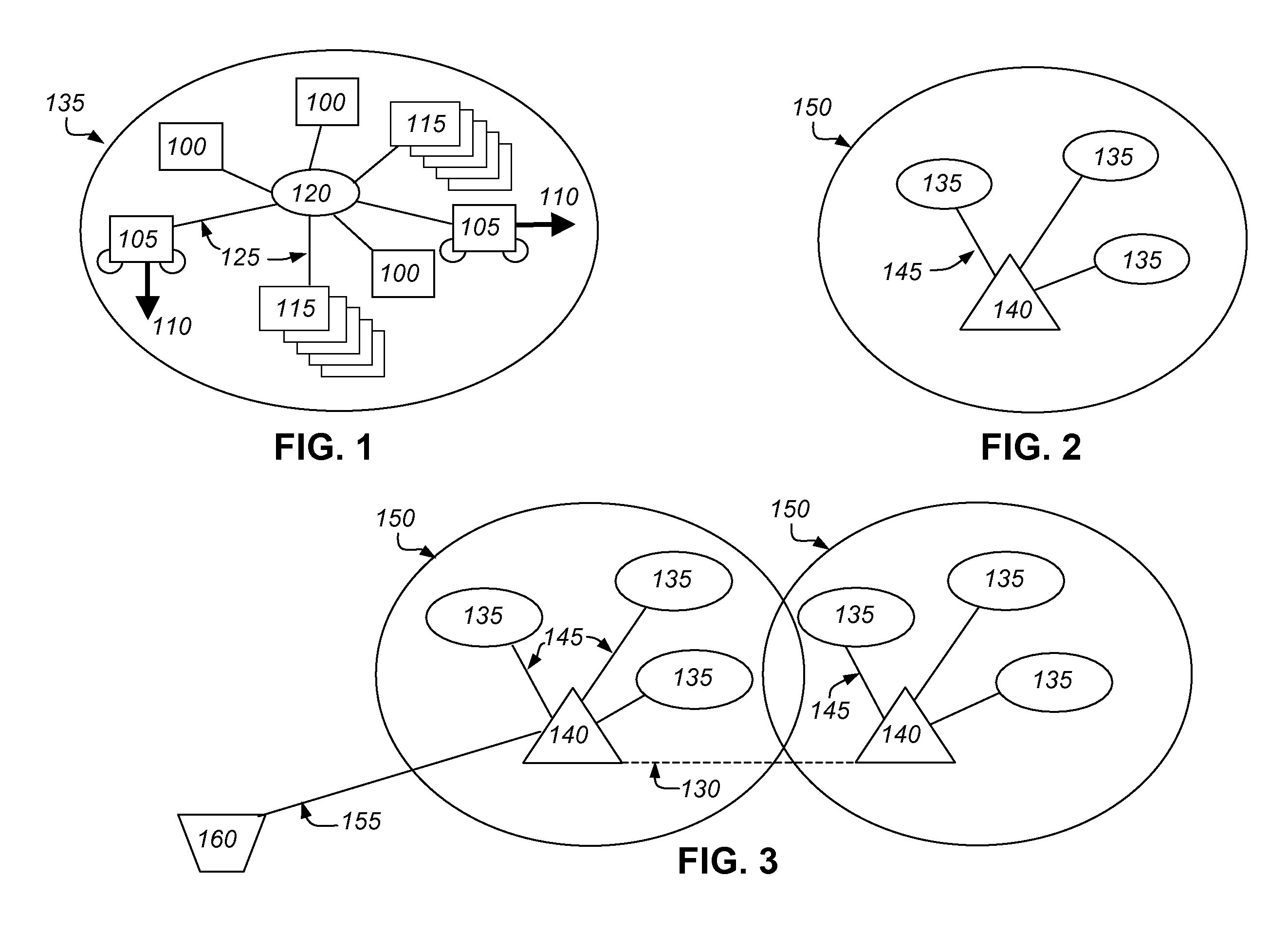
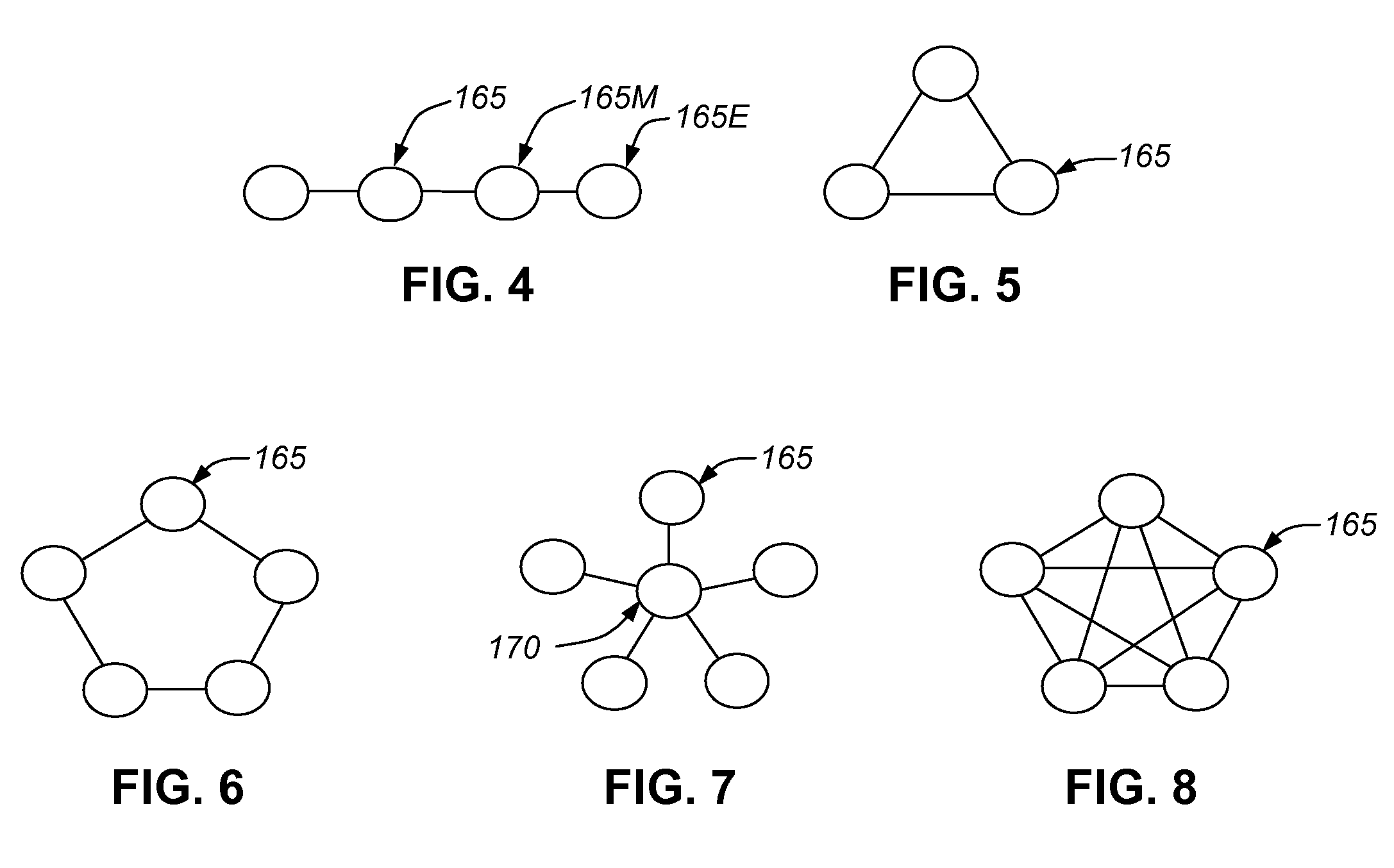
[0027]The present invention in one aspect is a novel
wireless network based on novel topological design principles, and means for its implementation. A principal objective of the design of the inventive
network topology is to limit the
impact on the
wireless network of a failure of a node or a normally operative
nodal link to another node or
station, including an internet gateway. Of principal concern is failure of internodal connections at higher levels in the hierarchy of nodes or stations. In the event of such failure, or in the event of the need to switch to an alternate link because of
traffic conditions in the network, etc.,
failover is facilitated because of the robust character of networks that implement the inventive topology. Fulfilment of these objectives tends to limit the increase in message
traffic congestion throughout the network that is consequent upon the failure of a node or link or upon increased local traffic. These design objectives are achieved through the exploitation of limited diversity and redundancy of peer-to-peer and point-to-point
nodal links, and preferably configuring the network according to a flower topology selected in accord with the general principles of the invention while taking into account the area served, traffic density and number of expected users.
[0029]In one aspect, the invention provides a
network structure that facilitates traffic shifting when an internet gateway fails. In that event, the backhaul
station (if it is still operational) may simply
relay message traffic to another backhaul
station with an internet gateway, along its peer-to-peer data links. Alternatively the backhaul station (if it is still operational) may return the message to the originating access point (in a point-to-point and hierarchical network
nodal communication) and command the access point to divert that message and all further messages via the access point's alternative backhaul station link until further notice. Alternatively (if the backhaul station and internet gateway are both non-operational) a command may be routed from another network traffic controlling station via the alternate backhaul station or via adjacent access points to the access point of concern, instructing that all traffic be routed through the alternative backhaul station until further notice or until repairs are reported. Alternatively the access point may be able to detect the failed backhaul station link on its own and switch to an alternate link. Preferred embodiments of the invention enable all of the foregoing
modes to be operational in the appropriate circumstances. Routing under direction from various monitoring nodes may be utilized to optimize, to the extent possible,
traffic flow throughout the partially failed network.
[0031]Another way of looking at the redundancy /
failover principle of the present invention in a
subnetwork context is to observe that subnetworks may be considered as physical entities but they may also be considered as logical entities. Nodes in the physical entities are wirelessly interconnected in accordance with a preferred topology, as discussed above. But from a logical point of view, a
subnetwork may comprise nodes that are interconnected via routers to a variable selection of other nodes. As mentioned previously, it is possible to divide a
physical network into several subnets by configuring different host computers to use different routers. In such latter cases, the “
logical topology”, or more precisely the logical analogue of topology, should be, for each subnet or at least for selected subnets, the logical equivalent of a triangular-mesh topology. This implies that there should be at least two available links between a given station at one hierarchical level and immediately available stations at the next level (up or down, as required). Looking at logical subnetworks, one simply applies to a logical structure (or to the possible variants thereof) the logical equivalent of a preferred triangular mesh topology according to the invention. If this approach is taken, then
failover in the logical
subnetwork can be automatically implemented without difficulty.
[0037]Message traffic peer-to-peer hopping between access points will significantly increase
traffic congestion and slow down or disrupt a network. While it is an option for rerouting in the event of a backhaul station's failure, access point hopping is not desirable because hopping adversely affects the network. Like the
CANOPY® design, the present invention makes use of distributed network services and peer-to-peer (or backbone) nodal connections between nodes of the same type, but unlike
CANOPY®, the present invention intentionally makes limited use of nodal links from one node to another node in the network hierarchy. Unlike
CANOPY®, access point hopping is not the initial default method of re-routing of messages; it is avoided through the use of alternate linking to another backhaul station. In instances of multiple and adjacent backhaul station failure, access point hopping may be unavoidable, but unlike CANOPY® design, network design incorporating flower topology according to the invention either eliminates or restricts access point hopping, thus mitigating the effects of nodal failure on the network as a whole. Whereas the optimal functioning of a CANOPY® network depends upon active users (customers) whose wireless devices serve as
relay-station nodes in the network, the robustness of wireless networks according to the present invention is independent of whether any given customer or group of customers is logged into the network or not.
[0039]In preferred implementations of the invention, transceivers, transverters, repeaters, portable computers, logic circuits and associated controlling circuitry, all of which may be of conventional design or routine adaptations of conventional design, are mounted in weatherproof containers and mounted in close proximity to their antennae in order to reduce
cable transmission losses and avoid external interference from
proximate utilities such as power lines. The devices within such containers may be powered by standard mains supplies, or, especially in remote locations, by batteries recharged by non-conventional means (including wind or
solar energy sources). Especially in an
urban environment, these containers and associated antennae may be mounted on street lamps, utility poles or other prominent objects in order to provide local coverage and make cost-effective use of existing infrastructure. Containers and antennae may be camouflaged for aesthetic reasons. Antennae are preferably placed far enough from utility services to avoid interfering signals from adjacent utility services, including those from hardwired data transmissions through
Broadband Power Line (BPL) or Power Line Communications (PLC);
noise within discrete discernible bandwidths may be filtered out.
[0041]Preferred implementations of the invention are expected to provide platforms for relatively high reliability and speed of digital communication. Preferred designs of wireless networks in accordance with the invention are expected to be relatively robust in that they are capable of providing suitable alternative
signal paths and node connections in response to temporary loss of service of one or more
signal paths or network nodes.


