
Current protection apparatus and method

Active Publication Date: 2008-01-24
CYBERSWITCHINGPATENTS
View PDF19 Cites 87 Cited by
  • Summary
  • Abstract
  • Description
  • Claims
  • Application Information

AI Technical Summary

Benefits of technology

[0042]According to another aspect of the embodiments, the current sampling circuit may include a current sensing

Problems solved by technology

Early in the development of modern networking equipment such as routers, it was realized that at times a particular piece of network equipment might hang or “crash.” In such instances, a human operator often had to intervene by traveling to the location of the equipment and rebooting or power cycling the equipment in order to get that particular piece of equipment working.
However, load device LD4 may be system critical.
Another drawback for conventional PDU 130 is where one of the load devices, for example load device LD5, needs protection at a current lower than the overcurrent rating of circuit breaker 134.
Another drawback for conventional PDU 130 occurs when there is a temporary current surge in one of the load devices (LD1 to LD8).

Method used


Image

  • Current protection apparatus and method
  • Current protection apparatus and method
  • Current protection apparatus and method

Examples


example web

Connection Interfaces

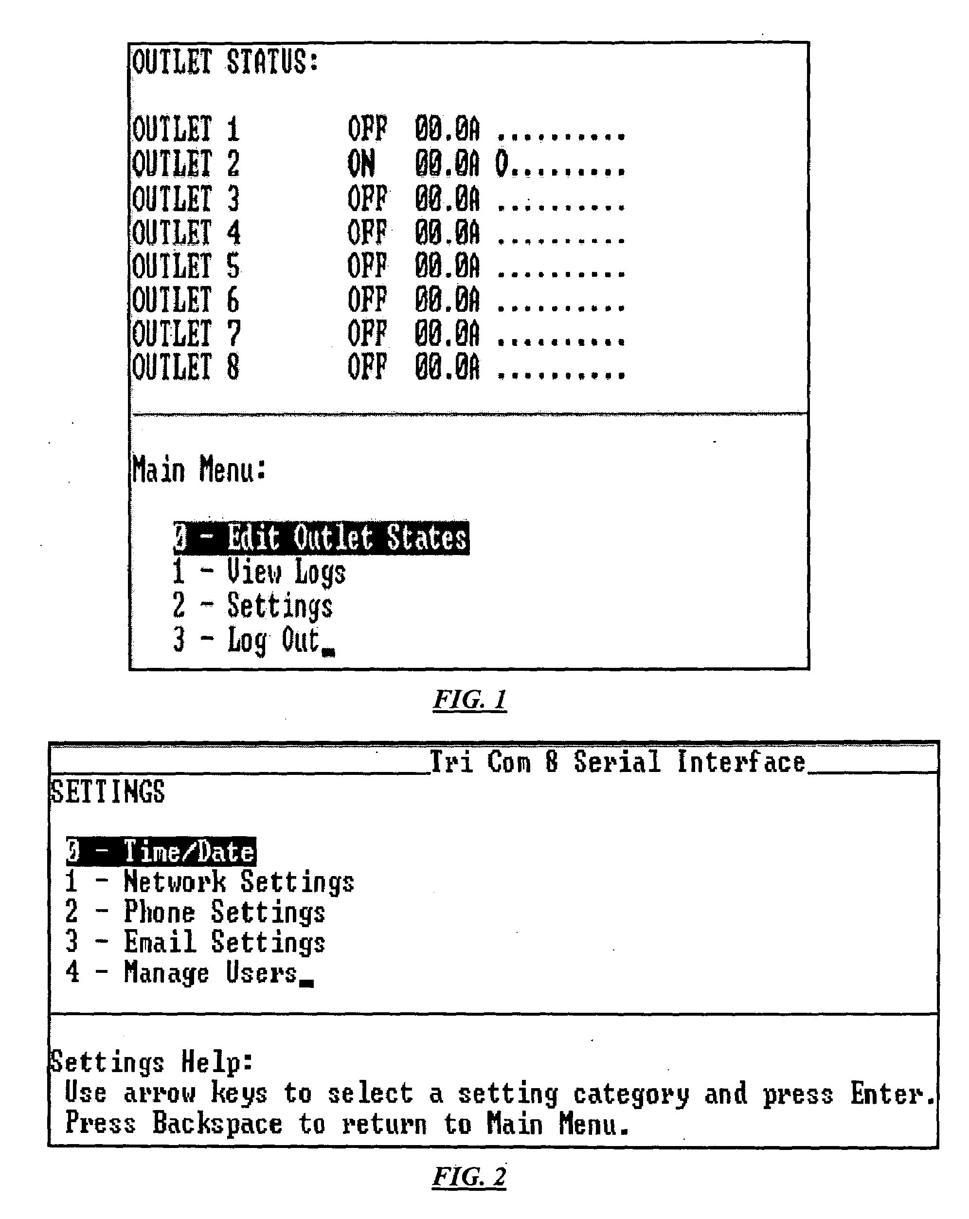
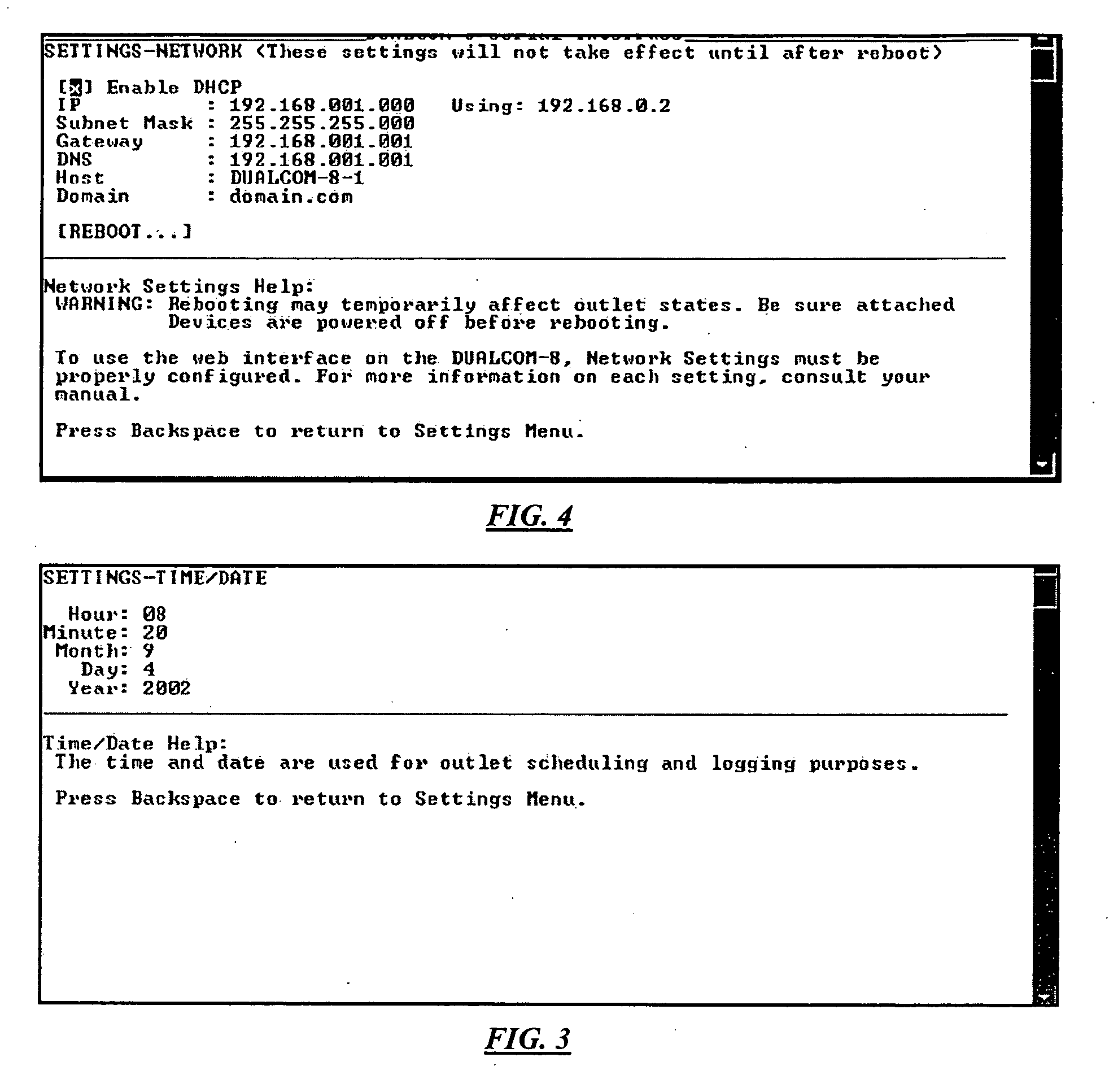
[0125]In specific embodiments, the invention includes a set of interfaces for a web-based connection. The discussion below and the referenced figures provide specific example embodiments of such interfaces. Once a network port (such as Ethernet) has been configured with the proper addressing, a user can access a SPS according to specific embodiments of the present invention through such things as a telnet session or through a web browser. According to specific embodiments of the invention, the Telnet session is text based and menu driven and has the same look and feel as the serial connection described above. A web interface is optimized for use in all web browsers, such as Internet Explorer.

[0126]To begin using the web interface, start a web browser and input an SPS's network identification (e.g., an IP and / or domain name address) Once found, an example SPS can prompt for a log on, for example using a popup window requesting a user name and password or alternat...

example hardware

Functional Components

[0162]FIG. 24 is a block diagram illustrating an example logic modules of a configurable power supply according to specific embodiments of the present invention. This is one example embodiment showing a number of different elements in one or more novel arrangements not of all which will be a part of all embodiments.

[0163]In this example embodiment, various functions as described above are provided by a microprocessor executing a stored-program, such as, for example, a Rabbit2000 Microcontroller and Memory. According to specific embodiments of the invention, the microcrontroller provides the logical execution ability to both control the outlets using a relay driver and relays as shown and also to provide communications ability through two or more interfaces, such as an Ethernet interface comprising an Ethernet connector (jack) and driver, a phone interface comprising a phone connector (jack) and phone DAA (Data Access Arrangement) & DTMF along with an audio proce...


PUM


Abstract

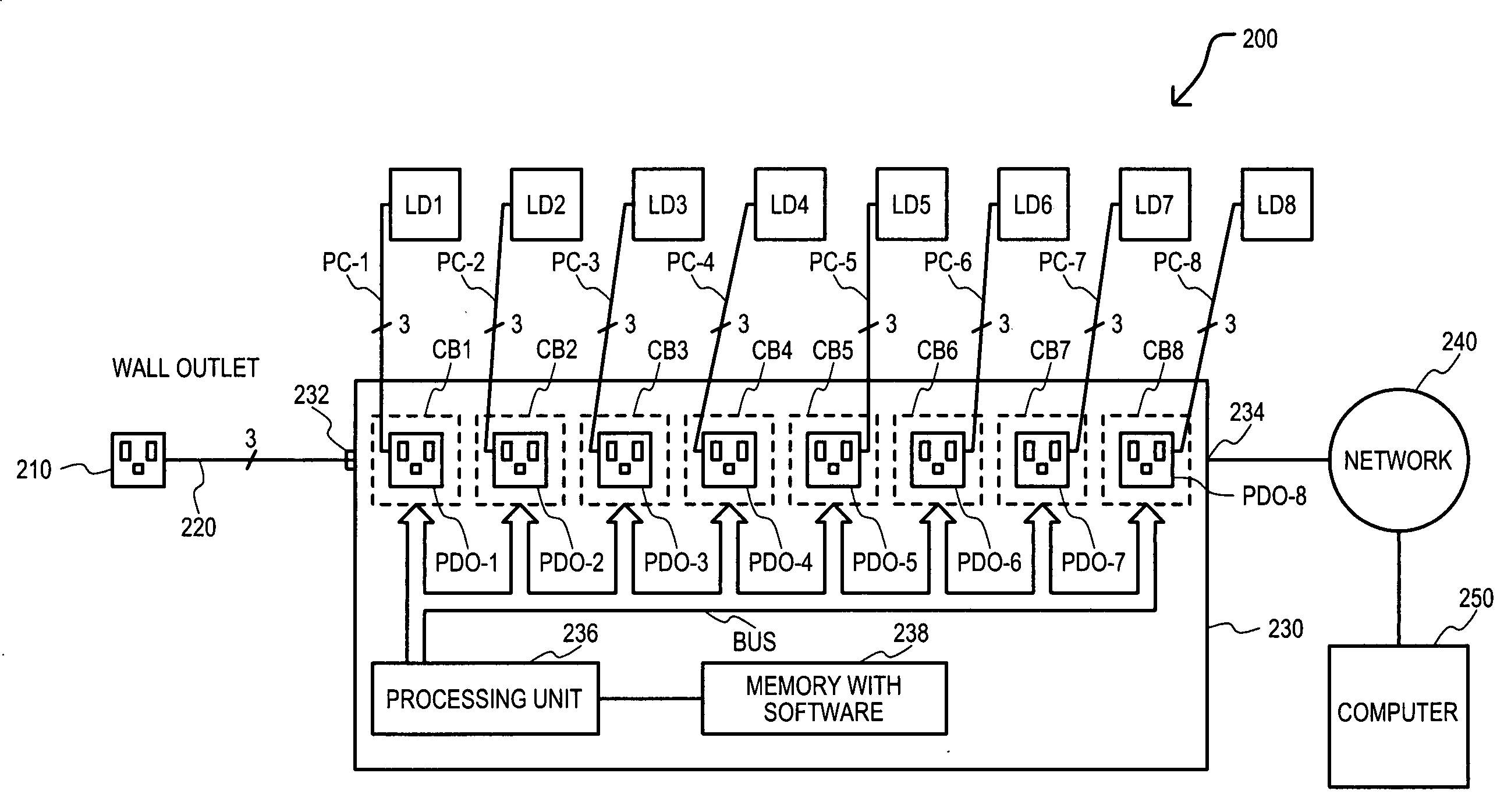
A current protection apparatus (200) and current protection method (1000) that may include programmable current protection characteristics has been disclosed. A current protection apparatus (200) may include a power distribution unit (230) with power distribution outlets (PDO-1 to PDO-8), each having a corresponding circuit breaker unit (CB1 to CB8). Each circuit breaker unit (CB1 to CB8) may operate in response to a processing unit (236) that can sample current values flowing between a respective power distribution outlet (PDO-1 to PDO-8) and a load device (LD1 to LD8). Processing unit 236 may operate under control of software stored on a memory (238) to control a switching circuit (320). Current protection characteristics for each circuit breaker unit may be independently programmed and / or altered by a user, for example by way of a computer (250). In this way, each power distribution outlet (PDO-1 to PDO-8) may have current rating characteristics independently provided for a particular load device (LD1 to LD8).

Description

CROSS REFERENCE TO RELATED APPLICATIONS[0001]This application claims priority from provisional patent application 60 / 378,342, filed May 6, 2002, U.S. patent application Ser. No. 10 / 431,333, filed May 6, 2003, and U.S. patent application Ser. No. 10 / 870,621 filed Jun. 16, 2004, all of which the contents are incorporated by reference herein.TECHNICAL FIELD[0002]The present invention relates generally to a current protection apparatus and more particularly to a current protection apparatus including a programmable characteristic and current protection method.COPYRIGHT AUTHORIZATION[0003]A portion of the disclosure of this patent document contains material which is subject to copyright protection. The copyright owner has no objection to the facsimile reproduction by anyone of the patent document or the patent disclosure, as it appears in the Patent and Trademark Office patent file or records, but otherwise reserves all (copyright or mask work) rights whatsoever.BACKGROUND OF THE INVENTI...

Claims


Application Information

Patent Timeline
IPC IPC(8): H02H3/08
CPCG06F1/26G06F1/266G06F2200/261H04L12/10H04L12/12H02H3/08H04L67/025H04L67/02H04L69/329Y02B60/34H04M11/007Y02B70/30Y04S20/20Y02D30/50
Inventor REYNOLDS, GREGORY A.REYNOLDS, CHARLES H.SILORIO, RON L.
Owner CYBERSWITCHINGPATENTS
Learn More