
Transforming device of power source and transformer thereof

a transformer and power source technology, applied in transformers/inductance coils/windings/connections, using reradiation, instruments, etc., can solve the problems of increasing manufacturing costs, affecting the operation of electronic devices, and complicating the design of transformers, so as to reduce the size and cost of the common mode filter to be added to the transforming device, the effect of improving the loss and reducing the noise of common mod

Active Publication Date: 2008-01-24
DELTA ELECTRONICS INC
View PDF9 Cites 10 Cited by
  • Summary
  • Abstract
  • Description
  • Claims
  • Application Information

AI Technical Summary

Benefits of technology

[0013]In view of the foregoing, the invention is to provide a transforming device of a power source and a transformer thereof capable of eliminating the common-mode noise to reduce the size and the manufacturing cost and to increase the power density.
[0016]As mentioned above, the transformer according to the invention has the shield disposed between the first winding and the second winding, and the transforming device according to the invention has the first capacitor, which is serially connected to and between the shield and the first winding and electrically connected to the first capacitor. Compared to the prior art, the invention can balance the common mode current between the first winding and the second winding through the cooperation of the shield and the first capacitor so that the common-mode noise can be reduced. In addition, the size and the cost of the common mode filter to be added to the transforming device can be reduced, the loss can be improved and the power density can be enhanced so that the efficiency in use may be enhanced.

Problems solved by technology

However, this kind of circuit often operates via high-frequency switching so that electromagnetic interference (EMI) tends to occur and thus influences the operation of the electronic device.
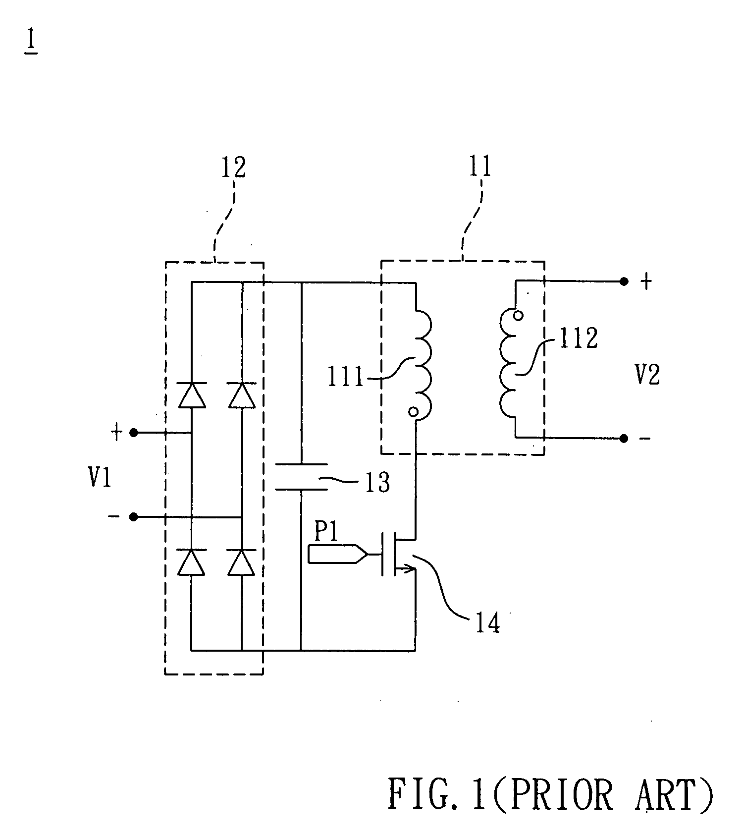
However, this method complicates the design of the transformer 11 due to the added winding 113, and also increases the manufacturing cost.
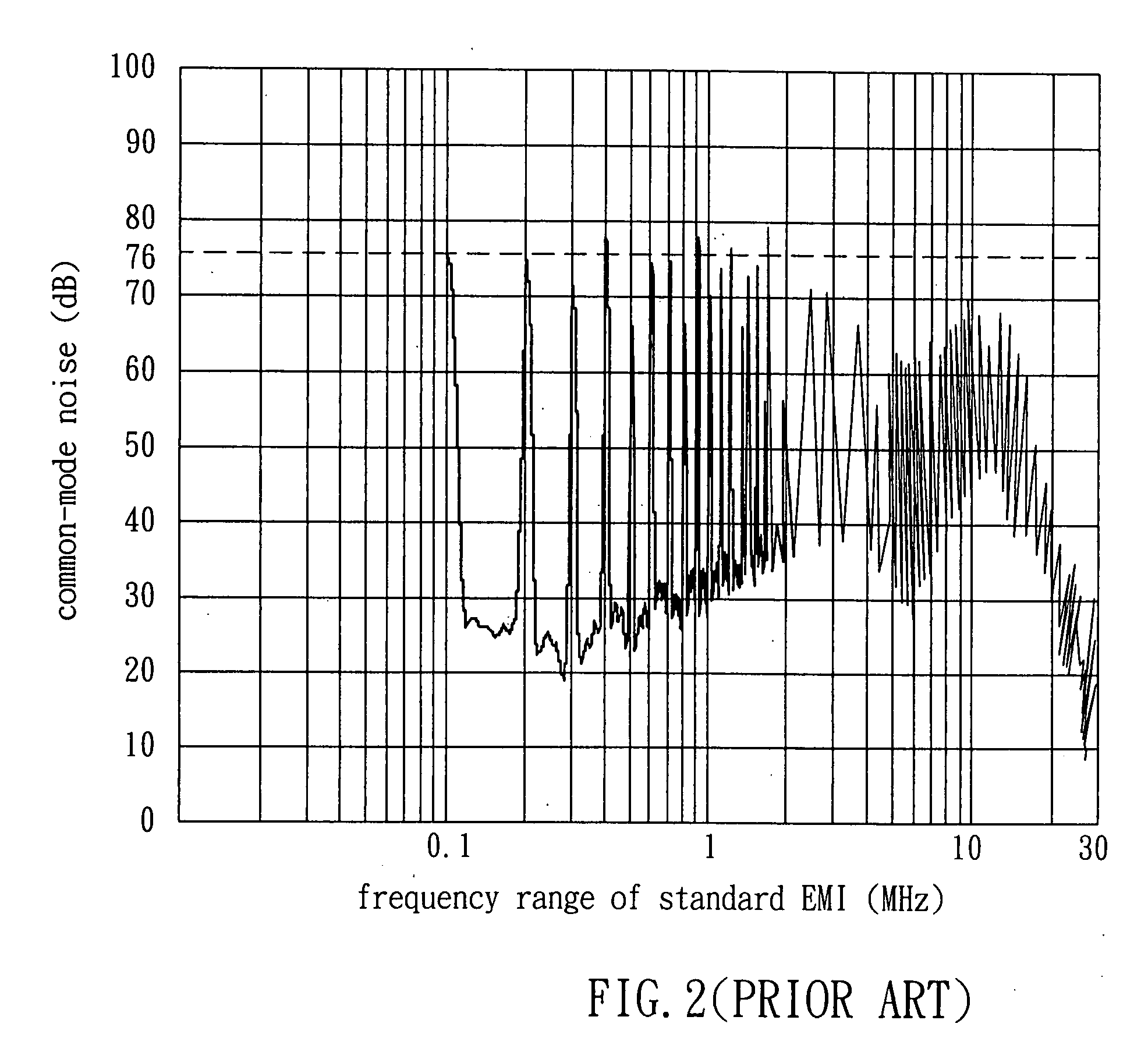
Hence, it is quite difficult to suppress the common-mode noise.

Method used


Image

  • Transforming device of power source and transformer thereof
  • Transforming device of power source and transformer thereof
  • Transforming device of power source and transformer thereof

Examples


Embodiment Construction

[0027]The present invention will be apparent from the following detailed description, which proceeds with reference to the accompanying drawings, wherein the same references relate to the same elements.

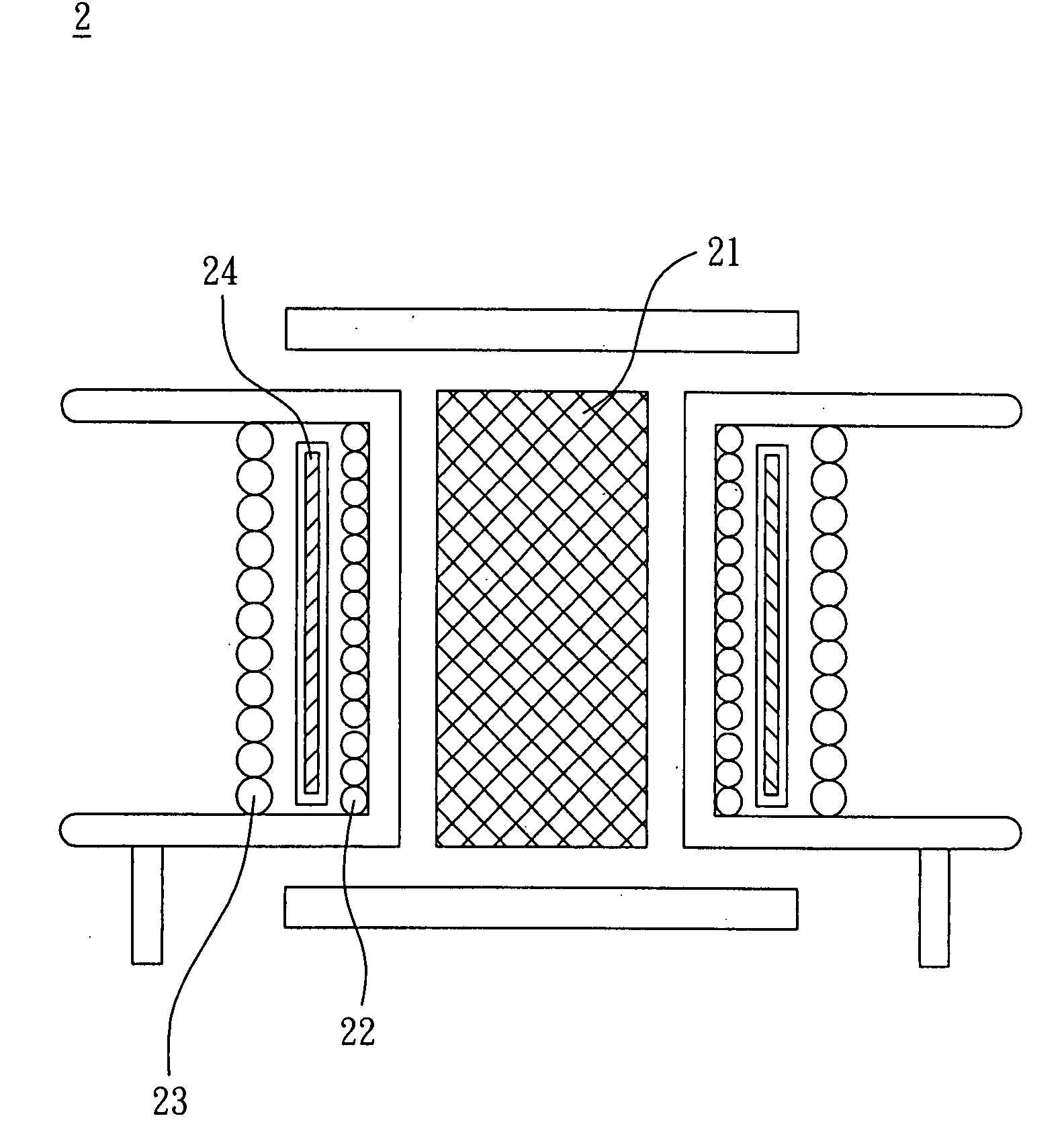
[0028]Referring to FIGS. 5 and 6, a transformer 2 according to a preferred embodiment of the invention includes a magnetic element 21, a first winding 22, a second winding 23 and a shield 24. The transformer 2 may be applied to a power switching device or an inverter. In this embodiment, the magnetic element 21 is made of, without limitation to, a magnet or a magnetic bolt, and the magnetic element 21 has, without limitation to, a cylindrical shape.

[0029]The first winding 22 is wound outside the magnetic element 21, and the second winding 23 is wound outside the first winding 22. The first winding 22 and the second winding 23 may be made by winding a single conductive wire, or separate conductive wires. Herein, the first winding 22 is the primary winding, and the second winding 23 is ...


PUM

PropertyMeasurementUnit
frequencyaaaaaaaaaa
frequencyaaaaaaaaaa
cylindrical shapeaaaaaaaaaa

Abstract

A transformer includes a magnetic element, a first winding, a second winding and a shield. The first winding is wound outside the magnetic element, the second winding is wound outside the first winding, and the shield is disposed between the first winding and the second winding.

Description

CROSS REFERENCE TO RELATED APPLICATIONS[0001]This Non-provisional application claims priority under 35 U.S.C. §119(a) on Patent Application No(s). 095126652 filed in Taiwan, Republic of China on Jul. 21, 2006, the entire contents of which are hereby incorporated by reference.BACKGROUND OF THE INVENTION[0002]1. Field of Invention[0003]The invention relates to a transforming device of a power source and a transformer thereof.[0004]2. Related Art[0005]Currently, electronic circuits are widely applied in electronic devices including transforming devices of power sources, such as power supplies and electric energy converters. However, this kind of circuit often operates via high-frequency switching so that electromagnetic interference (EMI) tends to occur and thus influences the operation of the electronic device. EMI may be divided into radiated EMI and conducted EMI according to the mode of interference transfer. Radiated EMI is transferred directly in an open space, and the conducted ...

Claims


Application Information

Patent Timeline
Patent Type & Authority Applications(United States)
IPC IPC(8): H01F27/36H01F27/33
CPCH01F27/36H01F27/33H01F27/363
Inventor LU, ZENG-YICHEN, WEI
Owner DELTA ELECTRONICS INC
Learn More