
Multiple-Reflection Delay Line For A Laser Beam And Resonator Or Short Pulse Laser Device Comprising A Delay Line Of This Type

a laser beam and multi-reflection technology, applied in the direction of laser details, optics, instruments, etc., can solve the problems of corresponding increase of the resonator length, and achieve the effect of reducing the physical length of the resonator, compact design and small siz

Inactive Publication Date: 2008-01-17
HIGH Q LASER
View PDF13 Cites 27 Cited by
  • Summary
  • Abstract
  • Description
  • Claims
  • Application Information

AI Technical Summary

Benefits of technology

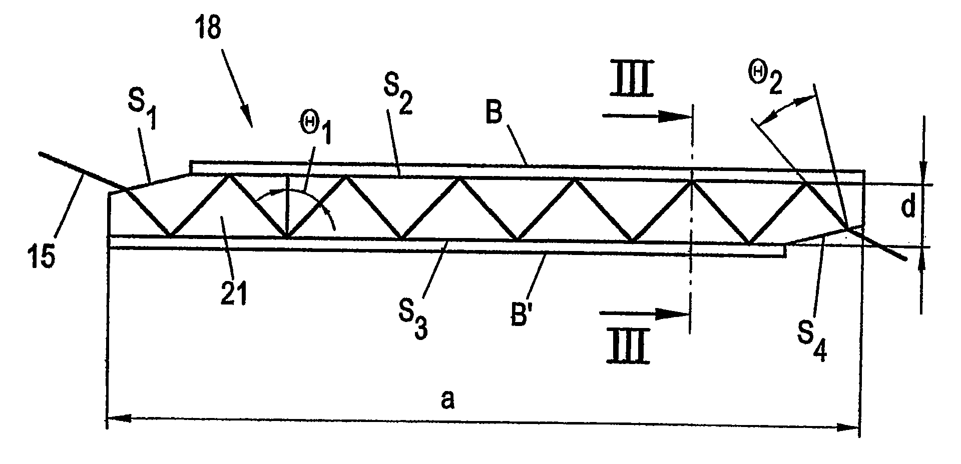
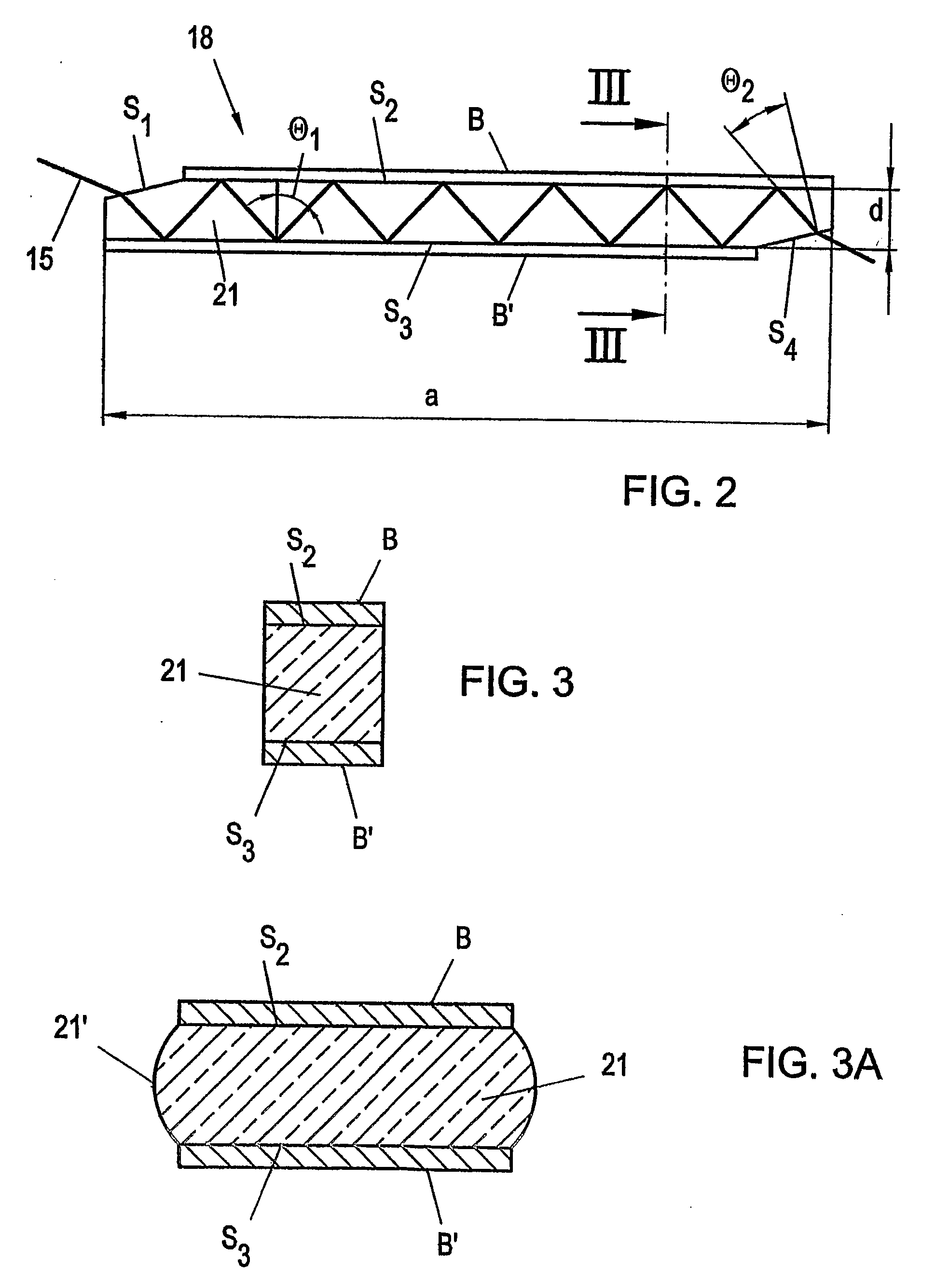
[0006] It is an object of the invention to provide a multiple-reflection delay line member of the initially defined kind, and a laser resonator and a short-pulse laser device including such a delay line member, with particularly small, compact designs being achievable. The invention is based on the finding that the physical length of a resonator can be reduced, if no air propagation path as is common with conventional short-pulse laser devices is employed, in which the optical length and the physical length are substantially identical, but if a propagation in a medium is used, which has a refraction index higher than air, in which case it will be feasible to indicate the physical length inversely proportionally to this refraction index, i.e. reduce the same. The invention is further based on the principle that the use of such a medium and the presence of interfaces between said medium and the environment (air), with accordingly differing refractive indexes, will allow for a total reflection of the laser beam if the latter impinges on this interface at an accordingly oblique angle. It is known that this critical angle of total reflection on an interface depends on the quotient of the two refractive indexes.

Problems solved by technology

Such comparatively low repetition rates, which, in turn, involve relatively long pulse circulation times in the laser resonator, however, result in a corresponding increase of the resonator length merely by way of calculation.

Method used


Image

  • Multiple-Reflection Delay Line For A Laser Beam And Resonator Or Short Pulse Laser Device Comprising A Delay Line Of This Type
  • Multiple-Reflection Delay Line For A Laser Beam And Resonator Or Short Pulse Laser Device Comprising A Delay Line Of This Type
  • Multiple-Reflection Delay Line For A Laser Beam And Resonator Or Short Pulse Laser Device Comprising A Delay Line Of This Type

Examples


Embodiment Construction

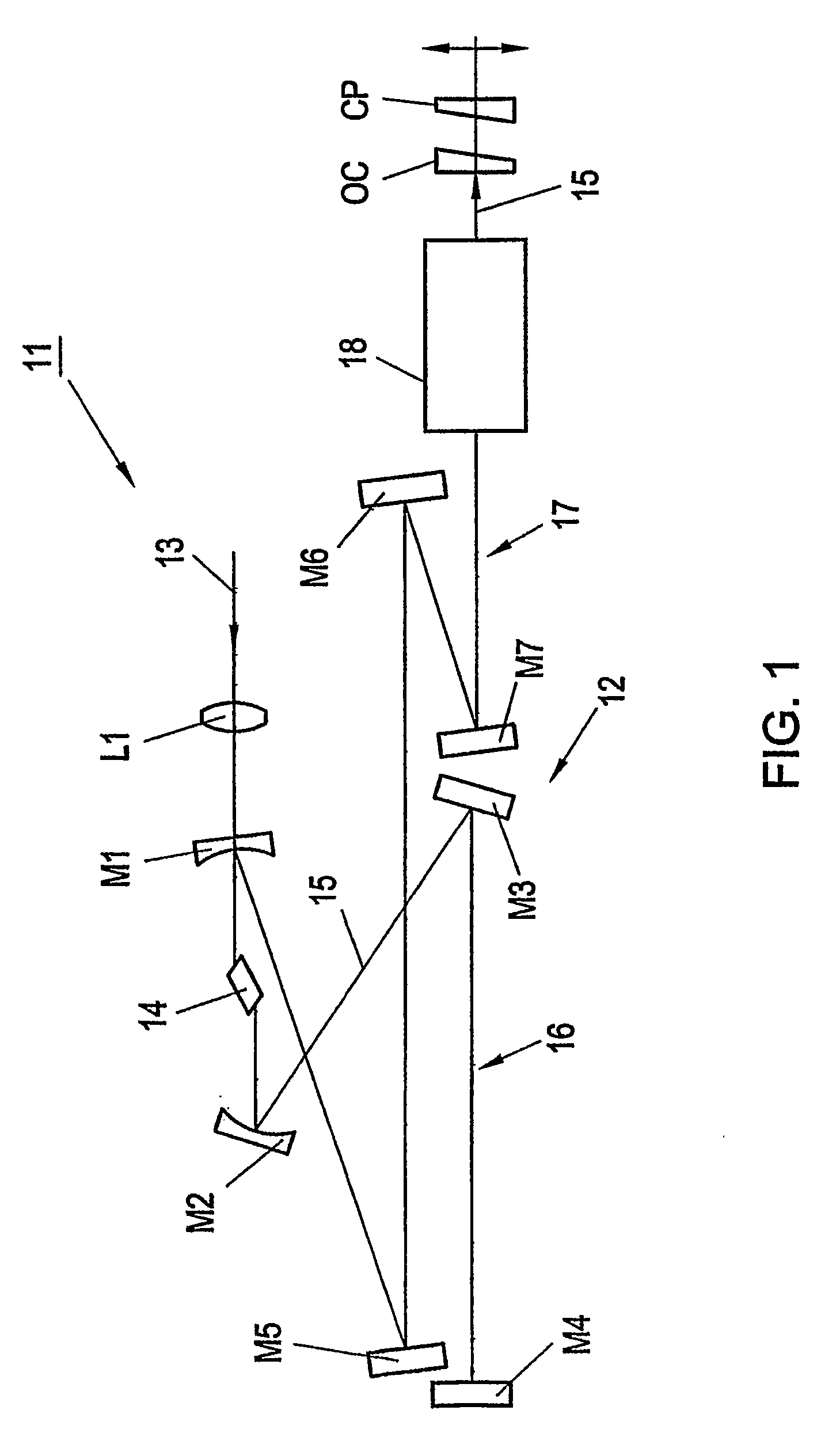
[0029]FIG. 1 schematically illustrates a conventional short-pulse laser device 11 known per se and implementing, for instance, the Kerr-lens mode locking principle known per se to generate short pulses.

[0030] The laser device 11 according to FIG. 1 comprises a resonator 12, to which a pump beam 13, e.g. an argon laser beam, is supplied. The pump laser itself, e.g. an argon laser, has been omitted in FIG. 1 for the sake of simplicity and belongs to the prior art.

[0031] After having passed a lens L1 and a dichroic mirror M1, the pump beam 13 excites a laser crystal 14, which is a titanium: sapphire (Ti:S) solid laser crystal in the present example. The dichroic mirror M1 is transparent for the pump beam 13, yet highly reflecting for the Ti:S laser beam 15. Said laser beam 15, i.e. the resonator beam, subsequently impinges on a laser mirror M2 and is reflected by the latter to a laser mirror M3. The laser mirror M3, in turn, reflects the laser beam to a laser mirror M4, from which th...


PUM


Abstract

A multiple-reflection delay line member for a laser beam, including mirror elements for the multiple reflection of the laser beam to reduce the dimensions of a laser resonator at a predetermined optical length, wherein the mirror elements are comprised of two oppositely arranged, longitudinally extending polished surfaces of a glass element which extends in one direction and which further comprises a polished laser beam entry surface as well as a polished laser beam exit surface, wherein the mirror element surfaces of the glass element are located between the entry surface and the exit surface and, with the laser beam, form an angle that at least equals the critical angle for total reflection, whereas the entry surface and the exit surface with the laser beam of the glass element define an angle that is smaller than the critical angle for total reflection.

Description

FIELD OF THE INVENTION [0001] The invention relates to a multiple-reflection delay line member for a laser beam, including mirror elements for the multiple reflection of the laser beam to reduce the dimensions of a laser resonator at a given optical length. [0002] Furthermore, the invention relates to a resonator and a short-pulse laser device including such a delay line member. BACKGROUND OF THE INVENTION [0003] In recent years, short-pulse laser devices have gained more and more interest, since they have enabled various applications in research and industry in view of the extremely short pulse durations in the femtosecond (fs) range at pulse peak powers of >1 MW. Short-pulse laser devices of this type having pulse durations in the fs range can, thus, be used for the time-resolved investigation of interactions between electromagnetic radiation and matter. On the other hand, the increasing miniaturization in material processing allows for the manufacture of superfine structures i...

Claims


Application Information

Patent Timeline
IPC IPC(8): H01S3/081G02B5/08
CPCH01S3/0606H01S3/0615H01S3/07H01S3/08004H01S3/17H01S3/0813H01S3/1112H01S3/1118H01S3/08013H01S3/00
Inventor TEMPEA, GABRIELSTINGL, ANDREAS
Owner HIGH Q LASER
Learn More