
Compact wideband slot antenna design with inverted co-planar waveguide feed

Inactive Publication Date: 2021-03-25
JUDD MANO D
View PDF0 Cites 1 Cited by
  • Summary
  • Abstract
  • Description
  • Claims
  • Application Information

AI Technical Summary

Benefits of technology

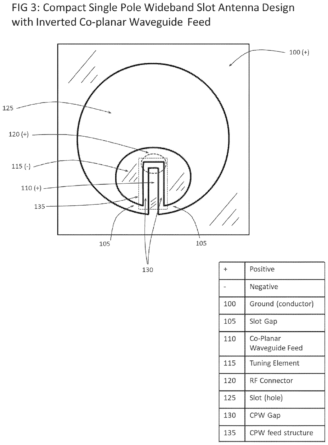
The invention changes the design of an antenna in a way that makes it smaller and more compact. The center trace is reversed and placed inside the slot structure, which eliminates the need for an extra space for the CPW feed. This results in a more compact and efficient design. The new design also uses the gap between the tuning element and the CPW inner trace as a new source point, which further reduces the size of the antenna. Overall, the invention allows for a smaller, more compact, and efficient antenna design.

Problems solved by technology

However, this is not the case when the model is migrated to very wideband antennas.

Method used


Image

  • Compact wideband slot antenna design with inverted co-planar waveguide feed
  • Compact wideband slot antenna design with inverted co-planar waveguide feed
  • Compact wideband slot antenna design with inverted co-planar waveguide feed

Examples


Embodiment Construction

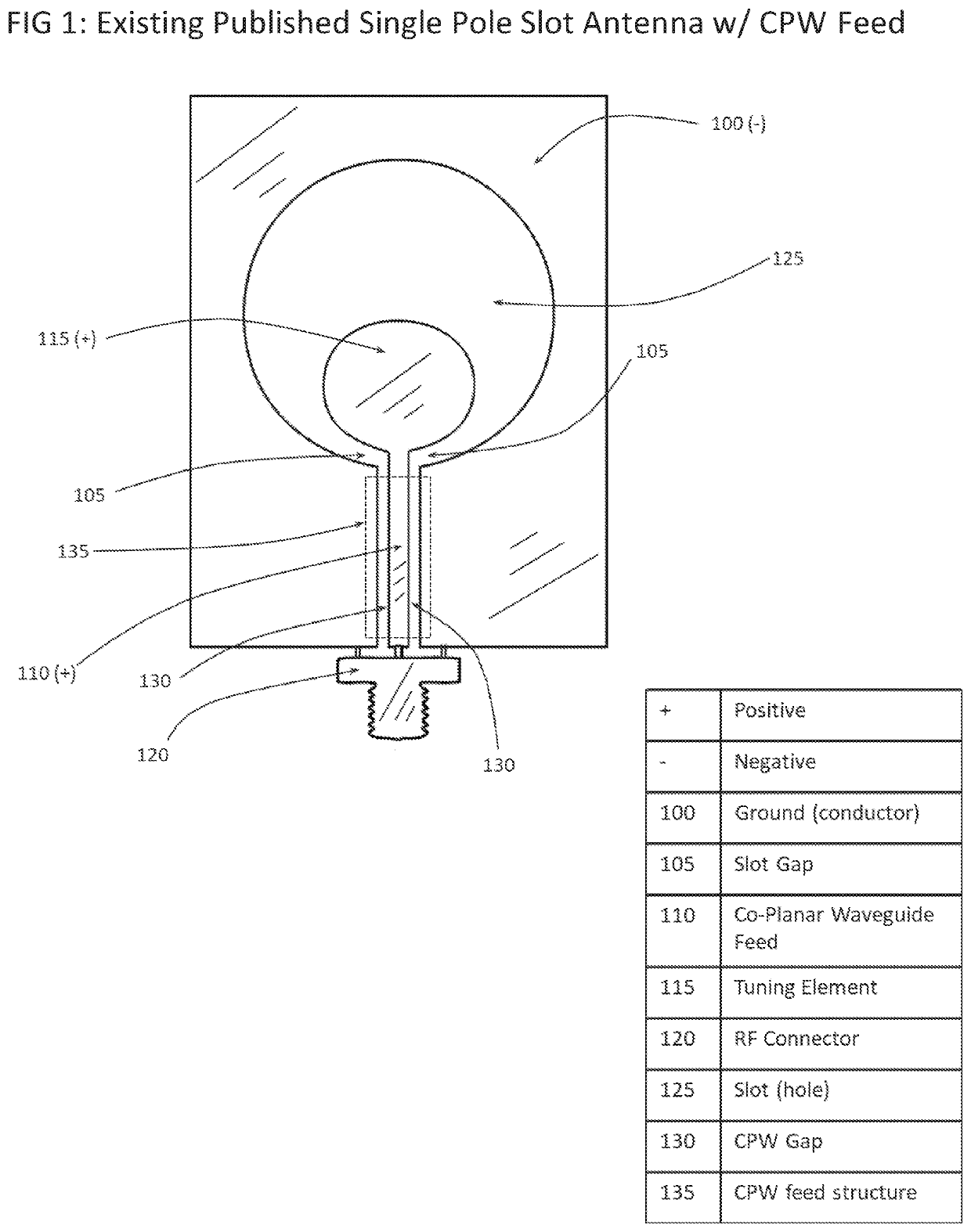
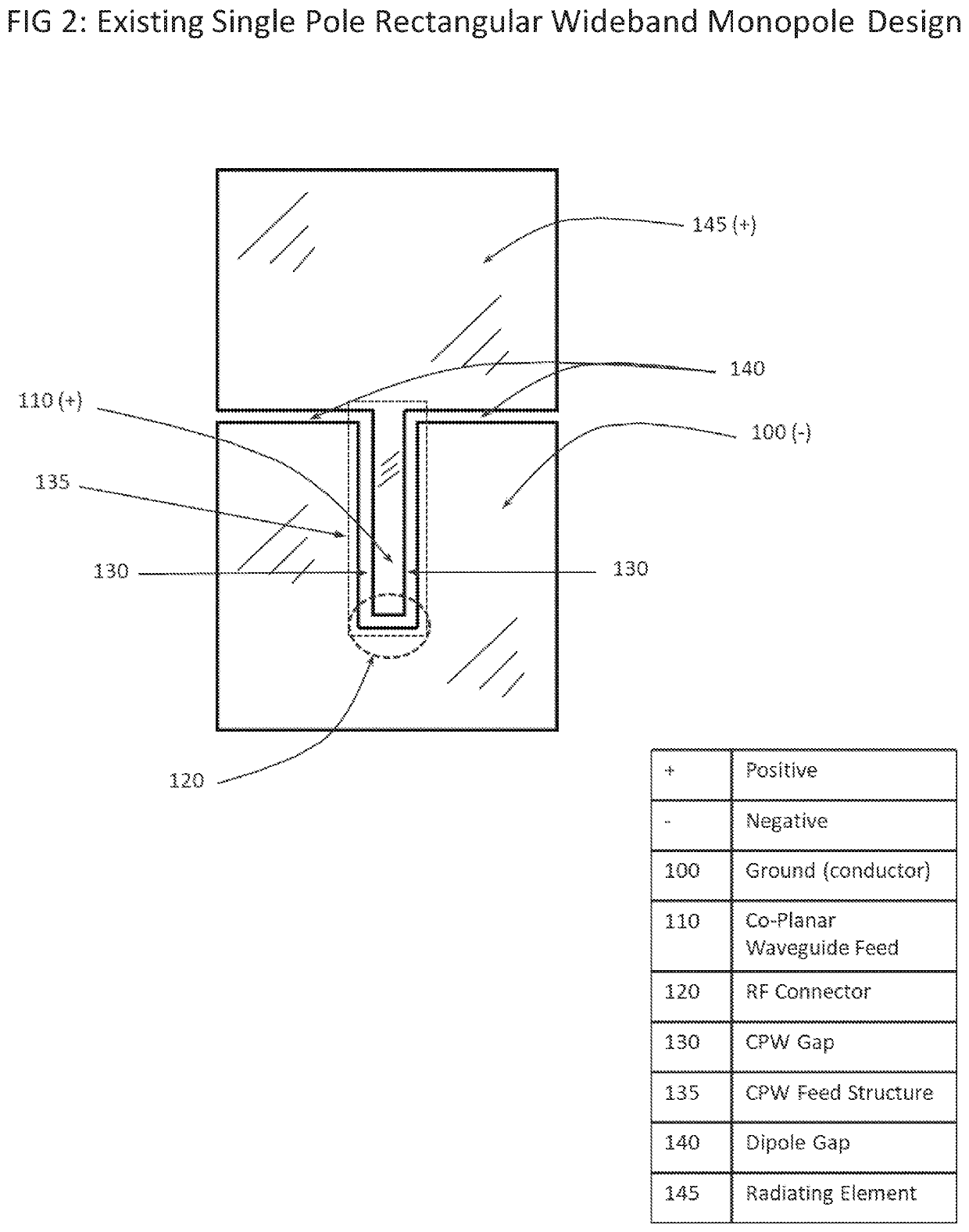
[0020]Wideband Slot antennas come in all sorts of sizes, shapes and configurations. However, single layer slot antennas, where all the conductive material or metal for the antenna is contained within a single flat or curved surface, require some variation of an external Co-Planar Waveguide (CPW) Feed structure. FIG. 1 shows a traditional single pole slot antenna fed with a conventional Tuning Element (115) connected to an external Co-Planar Waveguide (CPW) feed structure (135), with the CPW feed structure (135) also connected to an RF (example: SMA) connector (120). In this diagram, both the Slot (125) as well as the Tuning Element (115) are shown as circular shapes. In general, either or both of these components could be in almost any shape, including circular, elliptical, square, or rectangular. Additionally, the outer ground plane (100) outer edge dimensions could be almost any size or shape. However, the larger the ground plane (100), the better the antenna emulates the characte...


PUM


Abstract

A slot antenna where the inner CPW trace is migrated to the inside of the slot, rather than being external to the slot, and thus inverts the polarity of the center trace and puts the CPW feed section inside (within) the slot structure itself. Therefore, in this novel embodiment, the CPW feed does not increase the net size of the antenna, and results in a much smaller and / or compact design. In this fashion, now both the outer conducting surface and the CPW trace are connected and both negative (ground) polarity, whereas the tuning element is positive polarity. Thus the inner CPW trace becomes the same polarity as the outer ground conducting surface. This design is compact, without compromising an excessive amount of ground plane structure.

Description

[0001]The present application claims priority to the earlier filed provisional application having Ser. No. 62 / 744,995, and hereby incorporates subject matter of the provisional application in its entirety.BACKGROUND[0002]Slot antennas are equivalently “magnetic dipole antennas” which consist of a conductive surface or flat metal plate, with one or more slots (conductor hole) within the plate. When an inside edge is driven by an alternating current, the slot can radiate electromagnetic waves. The slot antenna is similar to electric dipole antennas; which radiate parallel with the long axis, however, a slot antenna has polarization perpendicular to the long axis. Wideband slot antennas can be characterized consisting of five (5) basic elements. The first (1) element is the outer conductive surface, or ground plane, that is often much larger than the slot itself. This conductive surface can be of many shapes such as circles, squares, or rectangles. This is often considered the “ground”...

Claims


Application Information

Patent Timeline
Patent Type & Authority Applications(United States)
IPC IPC(8): H01Q13/10H01Q1/52H01Q1/48
CPCH01Q13/10H01Q1/48H01Q1/52H01Q13/103H01Q13/106
Inventor JUDD, MANO D.
Owner JUDD MANO D
Learn More