Resilient device
a technology of resilient devices and sex, applied in the field of resilient devices, can solve problems such as stress urinary incontinence and other problems
- Summary
- Abstract
- Description
- Claims
- Application Information
AI Technical Summary
Benefits of technology
Problems solved by technology
Method used
Image
Examples
example 1
at Pessary
[0048]Approximately 1 foot of [straightened and etched] straightened and etched SE508 wire, 0.0315″ diameter was obtained. The tool pictured in FIG. 89 was made using conventional techniques known in stent art. In a smooth upswing, the wire was wrapped around the pins in the following order to create the pattern: P7, P3, P1CC, P3, P6CC, P3, P6, P4, P8CC, P5, P8, P5, P2CC, P5, P7, P1CC, P3, P7 (the wrapping was clockwise, unless indicated by “CC”). The zigzag wrapping pattern was smoothly discontinued and the final end of the wire was poked through holes in the fixture to secure it. A large hose clamp was wrapped around the fixture, over the zigzag portion. The clamp was tightened to keep the wires in position, but not so much as to compress the wires to the surface of the fixture. The wound wire was heat treated on the fixture for 3 minutes in a 505C (calibrated) salt pot, then quenched with water. The heat treated wire was removed from the fixture by unwinding it. The wir...
example 2
at Pessary
[0050]Approximately 1 foot of straightened and etched SE508 wire, 0.0315″ diameter was obtained. The tool pictured in FIG. 89 was made using conventional techniques known in stent art. In a smooth upswing, the wire was wrapped around the pins in the following order to create the pattern: P6, P3, P1CC, P3, P6, P4, P7, 6,3,1CC,3,6,4,7,5,2CC,5,7,4,6,3,1CC,3.P5, P2CC, P5, P7, P4, P6, P3, P1CC, P3. The zigzag wrapping pattern was smoothly discontinued and the final end of the wire was poked through holes in the fixture to secure it. A large hose clamp was wrapped around the fixture, over the zigzag portion. The clamp was tightened to keep the wires in position, but not so much as to compress the wires to the surface of the fixture. The wound wire was heat treated on the fixture for 3 minutes in a 505C (calibrated) salt pot, then quenched with water. The heat treated wire was removed from the fixture by unwinding it. The wire was trimmed at point 3 allowing for overlap along the...
PUM
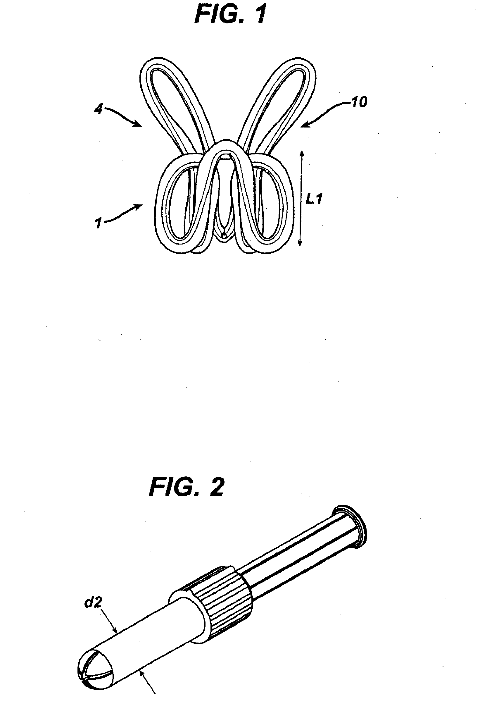
| Property | Measurement | Unit |
|---|---|---|
| length L1 | aaaaa | aaaaa |
| length L1 | aaaaa | aaaaa |
| equivalent diameter d 2 | aaaaa | aaaaa |
Abstract
Description
Claims
Application Information
 - R&D
- Intellectual Property
- Life Sciences
- Materials
- Tech Scout
- Unparalleled Data Quality
- Higher Quality Content
- 60% Fewer Hallucinations
Browse by: Latest US Patents, China's latest patents, Technical Efficacy Thesaurus, Application Domain, Technology Topic, Popular Technical Reports.
© 2025 PatSnap. All rights reserved.Legal|Privacy policy|Modern Slavery Act Transparency Statement|Sitemap|About US| Contact US: help@patsnap.com


