
Novel Strength Enhancing Insert Assemblies

a technology of insert assembly and insert, which is applied in the direction of sheet joining, branching pipes, fastening means, etc., can solve the problems of high stress concentration at the interface between insert and potting material, unsatisfactory reduction of specific strength, and inability to address the problem of minimization of insert assembly weight and a means to increase specific strength, so as to achieve high specific strength and reduce stress concentration

Inactive Publication Date: 2008-01-10
INDIAN INSTITUTE OF TECHNOLOGY BOMBAY
View PDF30 Cites 12 Cited by
  • Summary
  • Abstract
  • Description
  • Claims
  • Application Information

AI Technical Summary

Benefits of technology

[0014] The main object of the invention is to provide insert assemblies of high specific strength to reduce stress concentrations at locations where multidirectional stresses act on sandwich structures based on mapping stress distribution and failure initiation in sandwich structures.

Problems solved by technology

High density of metals / alloys increases the weight of insert assembly resulting in undesirable reduction in the specific strength.
Further, the difference in material properties at the interface between the insert and the potting material such as resin leads to high stress concentration at the interfaces between insert and potting material and between potting material and core.
Though this patent describes the method of installation of inserts into honeycomb sandwich structures, it does not address the issue of minimization of the insert assembly weight and a means to increase specific strength.
However, metal insert increases weight of the insert assembly resulting in reduction of specific strength.
However, these inserts suffer from the deficiency such that the surrounding potting material made of resin which is not a good conductor of heat that leads to thermal gradient along the radial direction.
This causes higher thermal stresses in the sandwich structure.
The use of metal for face-plate increases weight of insert assembly thereby decreasing the specific strength.
However it does not address the issue of weight of an insert assembly.
There are several drawbacks of this method and insert assembly.
Significantly high interfacial stresses develop between the alloy insert and the potting resin material.
It does not address the issue of enhancing the specific strength of insert assemblies.
Though geometry of the inserts and different methods of installation of these inserts into sandwich structures is addressed, the issue of minimization of the insert assembly weight and a means to increase specific strength of insert assembly has not been addressed.
There are no methods of reliably mapping stress distribution and prediction of failure initiation in sandwich structures with diverse geometrical configurations.

Method used


Image

  • Novel Strength Enhancing Insert Assemblies
  • Novel Strength Enhancing Insert Assemblies
  • Novel Strength Enhancing Insert Assemblies

Examples


example 1

Experimental Studies

[0135] Fabrication of Through-the-Thickness Insert Assembly

[0136] The insert assembly comprises of six constituents. They are: insert, potting material, foam core, lower face-plate, upper face-plate and the attachment. Lower face-plate and the upper face-plate are made of woven fabric E glass and epoxy resin using matched-die molding technique. The core is made of polyurethane foam. The attachment is made of mild steel. The material used for composite inserts is glass. The potting material is epoxy resin. Three insert assemblies were constructed using the above with aluminum, 2D woven composite and 3D woven composite as insert materials. [0137] Measurement of load, displacements and failure initiation [0138] The insert assembly was placed on a support ring and then located on Hounsfield Test Equipment—450 KS, 50 KN UTM. [0139] Compressive load was applied through the attachment on to the insert assembly. [0140] The displacement of the attachment, lower face-pla...

example 2

Comparison of Through-the-Thickness Inserts of Present Invention with Inserts of Prior Art

[0148] Using the method of the present invention, compressive load at failure initiation, failure function and specific strength of inserts are mapped for the prior art disclosed in U.S. Pat. No. 50,532,285 (corrugated aluminum insert) and for the insert (3D woven composite insert) of the present invention with the same geometry as used for the prior art (R=30 mm). The results are given in FIG. 10 and Table 5. Further, the geometry of the insert of the present invention was modified (R=10 mm) to reduce the insert assembly weight. With such a modified configuration, compressive load at failure initiation, failure function and specific strength of inserts are mapped. From FIG. 10 and Table 5, it is established that the inserts of the present invention are having higher specific strength compared to the insert of prior art.

TABLE 5Specific strength of through-the-thickness inserts with corrugate...

example 3

Analytical Studies with Different Insert Materials

[0149] Using the experimentally validated method for mapping of stresses, displacements and failure initiation, the results for aluminum, 2D woven composite, 3D thermoelastic isotropic woven composite, 3D woven composite, 3D woven composite with multiple inserts and 3D functionally gradient woven composite are obtained for the geometrical configuration of the insert assembly as given in Table 6. Material properties of the insert assembly are presented in Tables 7 and 8.

[0150] Maximum displacement, maximum normal stress and maximum shear stress corresponding to maximum compressive load at failure initiation are presented in Table 9. Specific strength of insert for different materials is also presented in Table 9. Failure function as a function of compressive load for different insert materials is presented in FIG. 11.

[0151] Percentage increase in specific strength of insert and percentage decrease in mass of insert for the composit...


PUM


Abstract

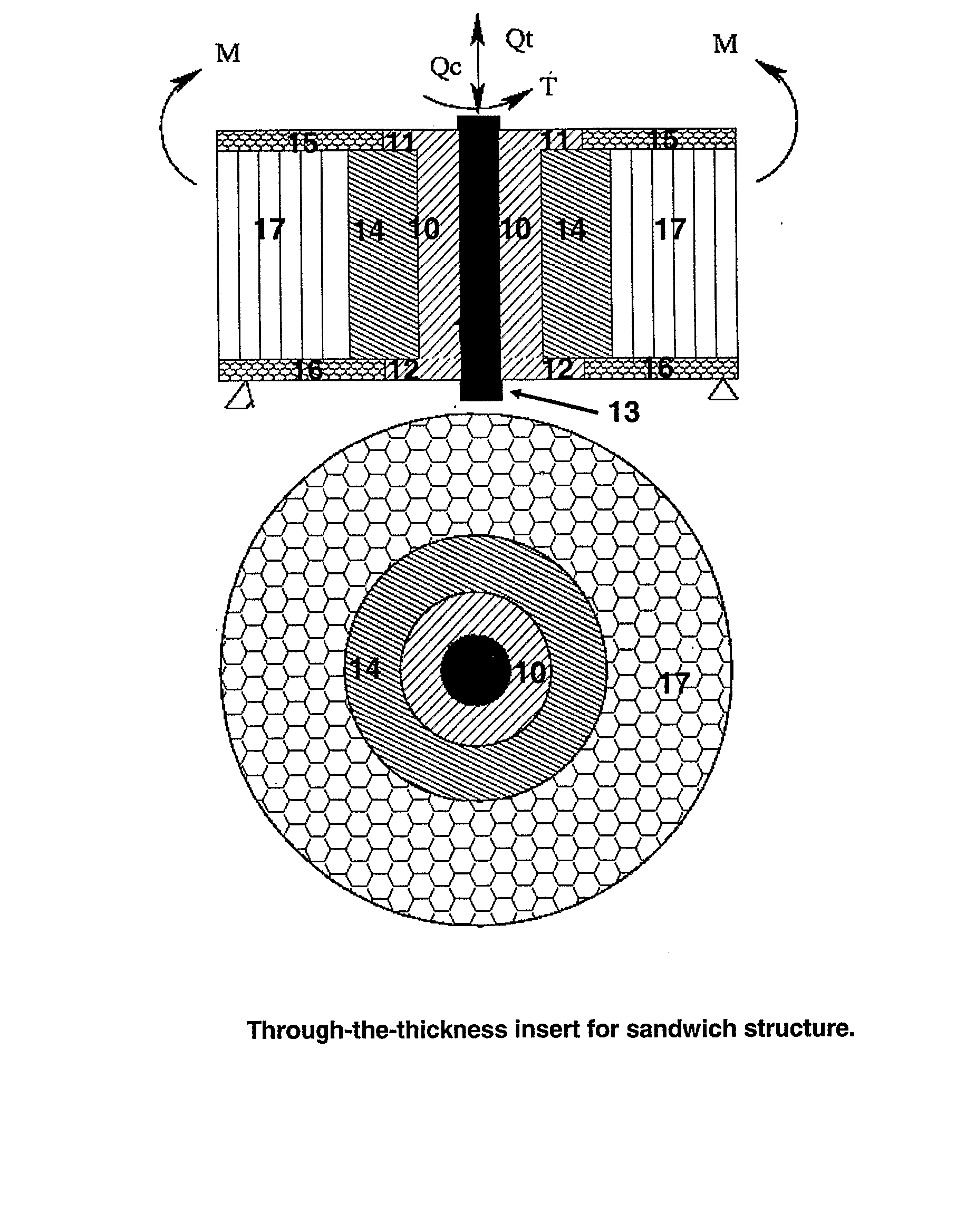
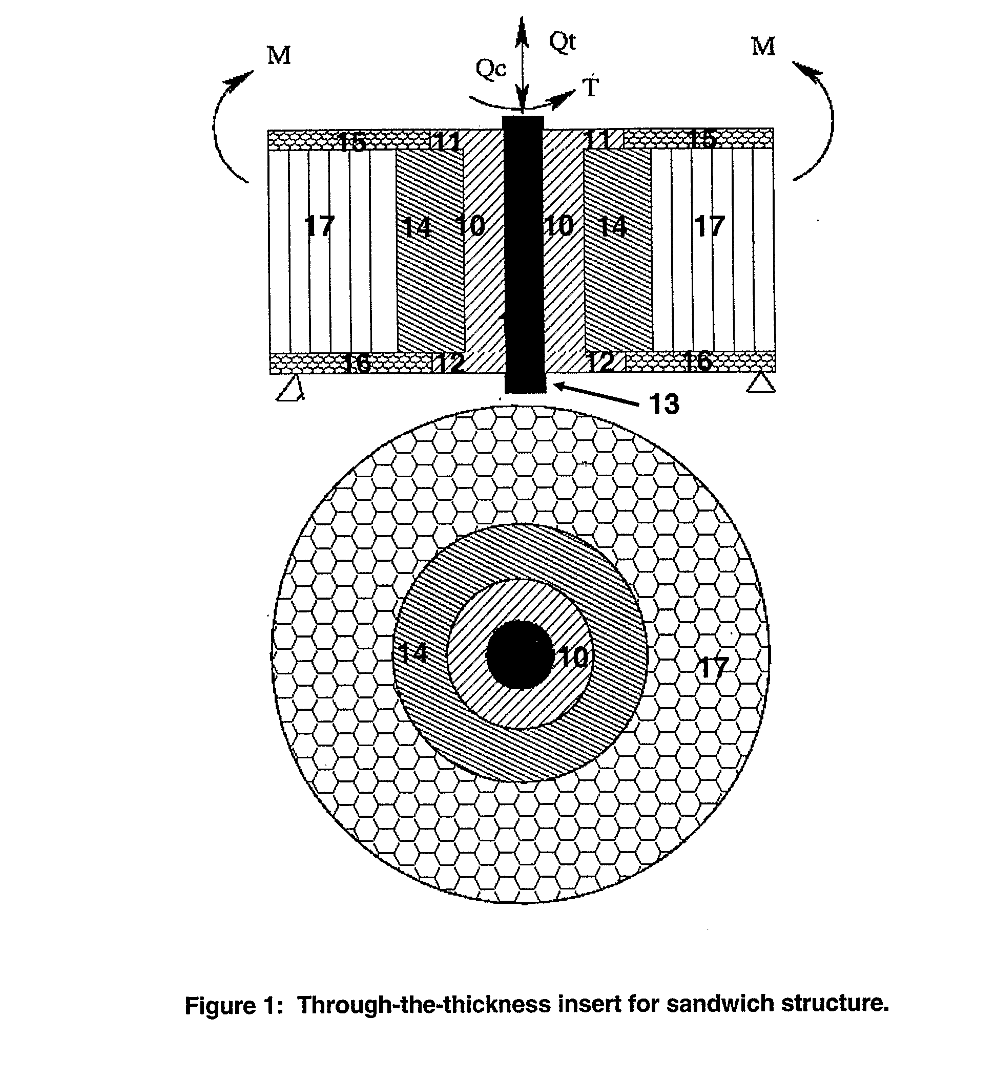
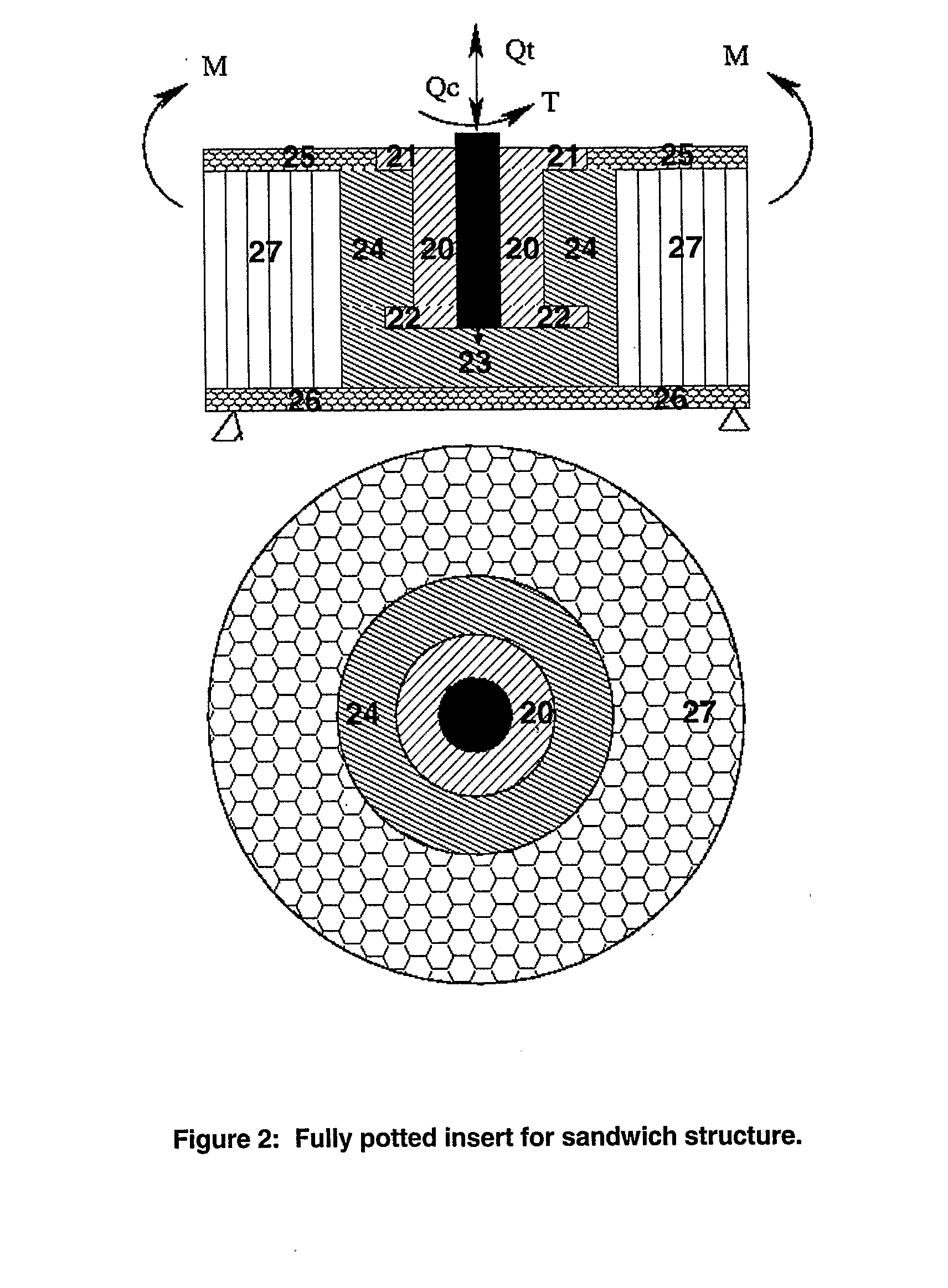
Insert assemblies of high specific strengths to reduce stress concentration at locations where Multidirectional stresses act on sandwich structures have been designed based on mapping stress distribution and failure initiation. The insert assembly comprises of insert (10, 20, 30), potting material (14, 24, 34), core (17, 27, 37), lower face plate (16, 26, 36), Upper face-plate (15, 25, 35) and attachment (13, 23, 33). The insert materials are selected from 2D woven composites, 3D thermoelastic isotropic woven composites, 3D woven composites, 3D woven composites with multiple inserts and 3D functionally gradient woven composites. Specific strengths of inserts (10, 20, 30) of present invention are higher than the inserts of prior art.

Description

FIELD OF THE INVENTION [0001] This invention relates to insert assemblies of high specific strength to reduce stress concentrations at locations where multidirectional stresses act on sandwich structures designed based on mapping stress distribution and failure initiation. BACKGROUND OF THE INVENTION [0002] Light weight sandwich structures are used in structural applications such as vehicles, aerospace industry, framework etc. because of their superior strength and stiffness properties along through-the-thickness direction under bending loads. The use of inserts is essential to strengthen the sandwich structures to withstand localized loads. Further, when the external members or sub-structures are attached to sandwich structures, inserts become a necessity. [0003] The specific strength of an insert assembly is a ratio of load at failure initiation to weight of the insert assembly which should be as high as possible to achieve effective utilization of sandwich structures with inserts...

Claims


Application Information

Patent Timeline
IPC IPC(8): F16B5/01
CPCY10T403/4671F16B5/01F16B2200/205
Inventor NAIK, NIRANJANGANJI, NAGESWARA
Owner INDIAN INSTITUTE OF TECHNOLOGY BOMBAY
Learn More