Cleaning method and cleaning apparatus

a cleaning method and cleaning technology, applied in the direction of photomechanical equipment, instruments, originals for photomechanical treatment, etc., can solve the problems of difficult purging of remaining additives from the end pipe in the rinsing process, damage to the fine structure, etc., to prevent the flow of liquidized additives and reduce the pressure in the substrate cleaning bath

Inactive Publication Date: 2008-01-10
SONY CORP
View PDF1 Cites 7 Cited by
  • Summary
  • Abstract
  • Description
  • Claims
  • Application Information

AI Technical Summary

Benefits of technology

[0032]It is desirable to provide a cleaning method and a cleaning apparatus in which additives remaining within pipes can be purged sufficiently after a wafer is cleaned.
[0040]In the cleaning method and the cleaning apparatus according to the embodiments the present invention, the residual additive can be sufficiently purged from the additive pipe. Therefore, when a pressure in the substrate cleaning bath is reduced (when the pressure in the substrate cleaning bath is returned to an atmospheric pressure) after the cleaning processing and the rinse processing, it is possible to prevent liquidized additives from flowing into the processing chamber. As a result, such problems as a fine structure of an object being damaged by the liquidized additive and the object being wet can be prevented. Further, even in the case where another additive is added to the object using the same pipe in the subsequent processing, additives can be prevented from being mixed and hence an intended processing can be carried out.

Problems solved by technology

However, there still remains a problem that an additive dissolved into a supercritical fluid remaining in an end pipe is liquidized in the reduced-pressure state after the wafer is cleaned, entered into the substrate cleaning bath to wet the wafer and as a result the fine structure may be damaged.
Further, since the semiconductor wafer is cleaned and rinsed with the supercritical fluid under an extremely high pressure, it is difficult to purge the remaining additives from the end pipe in the rinsing process.

Method used


Image

  • Cleaning method and cleaning apparatus
  • Cleaning method and cleaning apparatus
  • Cleaning method and cleaning apparatus

Examples


first embodiment

[0056]Next, a cleaning method for cleaning an object, for example, a semiconductor wafer (hereinafter referred to as a “wafer”) using the supercritical cleaning apparatus 1 according to the embodiment will be described with operation processes.

[0057]FIGS. 4A to 4E are respective diagrams showing those operation processes. It should be noted that open valves represent valves in the open state and that solid valves represent valves in the closed state in FIGS. 4A to 4E. Also, thick broken lines represent flows of supercritical CO2 and thick solid lines represent flows of additives and residuals thereof.

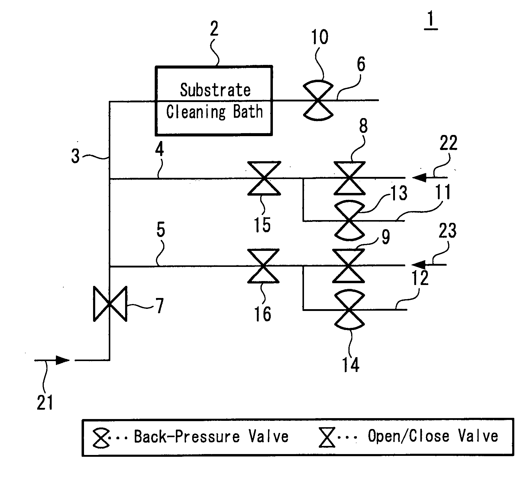
[0058]First, a wafer is accommodated and placed within the substrate cleaning bath 2. Next, as shown in FIG. 4A, cleaning processing is carried out. Specifically, the open / close valve 7 and the back-pressure valve 10 are opened so as to retain a supercritical state and a supercritical CO2 21 heated and pressurized is supplied to the substrate cleaning bath 2 through the main pipe 3. Fur...

second embodiment

[0064]Next, a cleaning method for cleaning an object using the supercritical cleaning apparatus 1 shown in FIG. 3 will be described with the operation processes.

[0065]FIGS. 5A to 5E are diagrams showing those operation processes. It should be noted that open valves represent valves in the open state and that solid valves represent valves in the closed state in FIGS. 5A to 5E. Also, thick broken lines represent flows of supercritical CO2 and thick solid lines represent flows of additives and residual additives.

[0066]First, a wafer is accommodated and placed within the substrate cleaning bath 2. Next, as shown in FIG. 5A, cleaning processing is carried out. Specifically, the open / close valve 7 and the back-pressure valve 10 are opened so as to retain a supercritical state and a supercritical CO2 21 heated and pressurized is supplied to the substrate cleaning bath 2 through the main pipe 3. Further, in the state in which the back-pressure valves 13 and 14 of the branch pipes 11 and 12 ...


PUM

PropertyMeasurementUnit
heightaaaaaaaaaa
pressureaaaaaaaaaa
temperatureaaaaaaaaaa

Abstract

A method of cleaning an object in a processing chamber by supplying a supercritical fluid with an additive and rinsing the object with the supercritical fluid alone includes the steps of: opening a back-pressure valve of a branch pipe branched from an additive pipe on the rinse processing; and purging a residual additive from the additive pipe by circulating the supercritical fluid alone into the additive pipe and the branch pipe.

Description

CROSS REFERENCES TO RELATED APPLICATIONS[0001]The present invention contains subject matter related to Japanese Patent Application JP 2006-189553 filed in the Japanese Patent Office on Jul. 10, 2006, the entire contents of which being incorporated herein by reference.BACKGROUND OF THE INVENTION[0002]1. Field of the Invention[0003]The present invention relates to a cleaning method and a cleaning apparatus using a supercritical fluid, applicable to cleaning of semiconductor substrates in a semiconductor manufacturing process or cleaning of substrates in a process of manufacturing a photo-mask or a liquid-crystal display substrate, for example.[0004]2. Description of the Related Art[0005]In most of semiconductor apparatus manufacturing processes, for example, patterning processes for forming electrodes of desired shapes of planes, wiring patterns and contact holes are carried out by etching patterns on an electrode layer, a wiring layer, an insulating layer and the like deposited on a ...

Claims


Application Information

Patent Timeline
Patent Type & Authority Applications(United States)
IPC IPC(8): C25F3/00B08B7/00G02F1/13G02F1/1333G03F1/82H01L21/027H01L21/304
CPCB08B7/0021H01L21/67057H01L21/02101G03F7/427
Inventor WATANABE, HIDEO
Owner SONY CORP
Why Eureka
Try Eureka