Micropump controlled by electrocapillary and gas pressures

a micropump and electrocapillary technology, applied in the field of micropump, can solve the problem that no satisfactory micropump has been constructed so far

Inactive Publication Date: 2007-12-27
POSTECH ACAD IND FOUND
View PDF2 Cites 10 Cited by
  • Summary
  • Abstract
  • Description
  • Claims
  • Application Information

AI Technical Summary

Benefits of technology

[0005]It is, therefore, an object of the present invention to provide a micropump to pump fluids, such as liquids or gases, by taking advantage of the electrocapillary effect due to the changes in surface tension at

Problems solved by technology

However, no satisfactory micropumps have been constructed thus far, which meet the technical specifications necessary for operation of the above demands.
For this reason, th

Method used


Image

  • Micropump controlled by electrocapillary and gas pressures
  • Micropump controlled by electrocapillary and gas pressures
  • Micropump controlled by electrocapillary and gas pressures

Examples


example 1

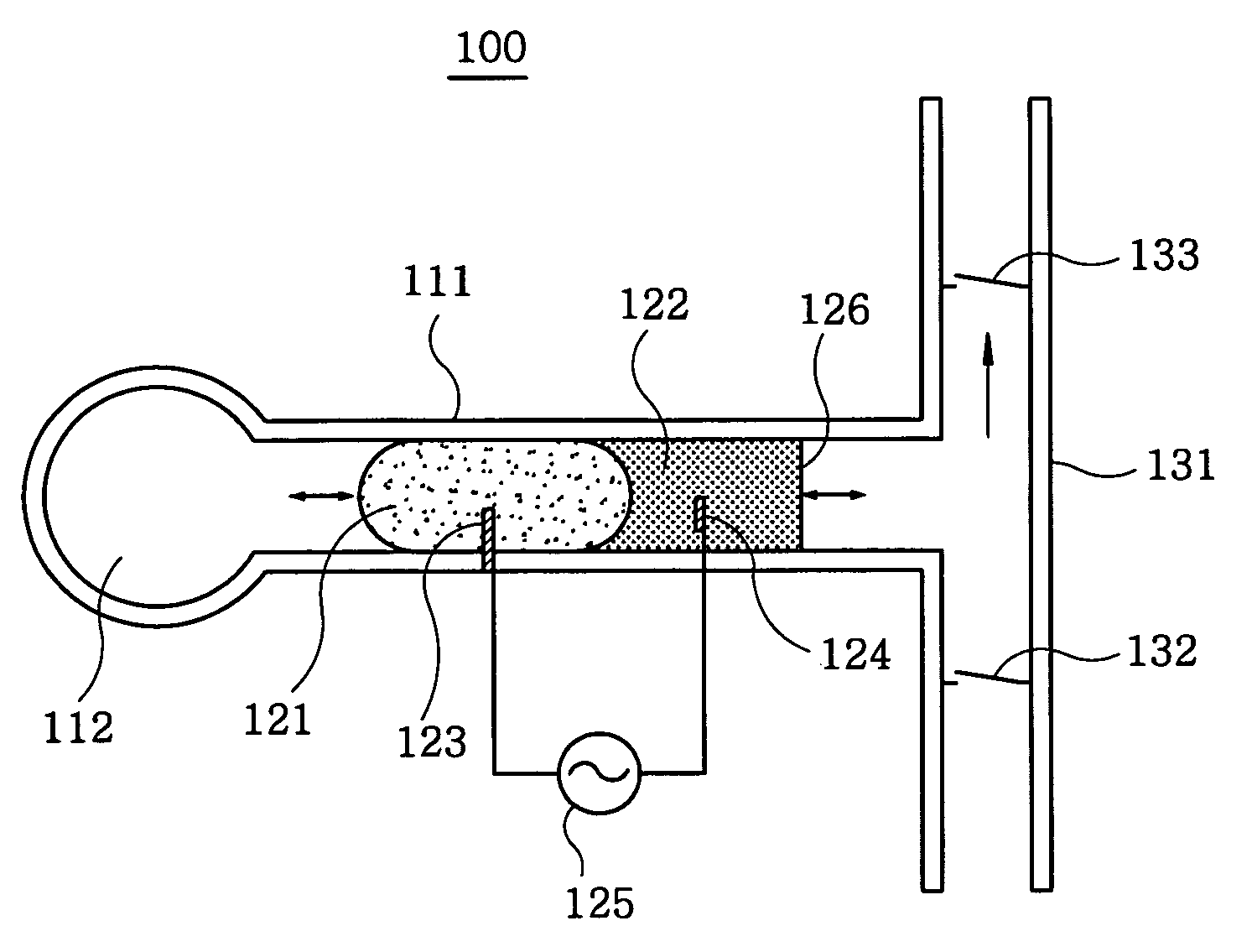
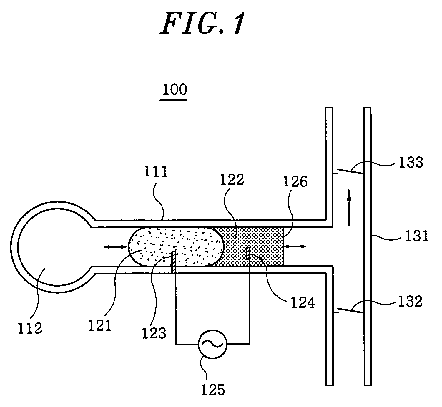
[0051]The pumping rate (flow rate) of the micropump is determined by the moving rate of the mercury column and the cross sectional area of the capillary tube. The moving rate is determined by the distance of the mercury column movement multiplied by the frequency of the square or AC waves applied. The maximum pumping rate is then expressed by Eq. 2:

Pumping rate=d·f·A  Eq. 2,

where d is the distance of the mercury column movement, f is the frequency of the AC or square pulse wave, and A is the cross sectional area of the capillary tube. The pumping rate may be adjusted by controlling any of these parameters.

[0052]When the change in surface tension of mercury was 5%, which was usually achievable with a half volt amplitude, the gas volume was 1.0 cm3, the radius of the capillary tube was 0.5 mm, and the frequency of the square or AC waves was 1 Hz, the pumped volume per one cycle was 0.79 μL / s at an atmospheric pressure of the gas and the distance of the mercury column movement of 1 mm,...

example 2

[0053]The same conditions were adapted as those in EXAMPLE 1 except that the gas volume was 0.1 cm3 and the radius of the capillary tube was 0.1 mm, the pumped volume per one cycle was 0.4 μL / s, the distance of the mercury column movement was 13 mm, and the pumping rate was 24 μL / min. When the length of the mercury column is to be 2 mm, the amount of the mercury column to be used is 0.000063 cm3, or 0.85 mg.

[0054]In summary, the micropump described in the present invention has the following characteristics: (1) a very small amount of liquids or gases can be pumped, (2) the size of the pump is small with its simple structure and the low construction cost, (3) the pump can be used to pump a wide variety of fluids including aqueous solution, nonaqueous solution, gases or the like, (4) no vibration and / or no noise is generated during its operation, (5) the flow and pumping rates can be easily controlled, (6) the pump can be arranged in any spatial orientation, (7) the pump may be applie...


PUM


Abstract

A micropump utilizes electrically controlled interfacial tension between a mercury column and an electrolyte solution in a capillary tube, and also uses the gas pressure in a confined chamber connected to the capillary tube as the restoring pressure. Accordingly, the pump operates without generating external jitter or noise, in vertical, horizontal, or in any orientation against the gravitational force. In this manner, the flow rate of the pumped fluid can be widely and conveniently controlled. Further, the micropump is small in size and simple in construction, and needs extremely small power consumption.

Description

FIELD OF THE INVENTION[0001]The present invention relates to a micropump for delivering fluid in small amounts; and, more particularly, to a micropump taking advantages of the change in surface tensions at the mercury / aqueous electrolyte interfaces caused by periodically changing potentials between two preset values.BACKGROUND OF THE INVENTION[0002]Reliable and reproducible micropumps have been in demands for continuous delivery of drugs or other biologically active substances, continuous operation of micro total analysis systems (pTAS) such as the lab-on-a-chip as well as other microanalysis apparatuses, continuous injection of reactants in a reaction vessel such as in miniaturized fuel cell systems, printer heads, and active cooling of microelectronics.[0003]Technologies including piezoelectric devices and those utilizing electrocapillary effects and reversible electrochemical gas evolution-dissolution reactions have been employed to construct micropumps. However, no satisfactory ...

Claims


Application Information

Patent Timeline
IPC IPC(8): G01N27/00
CPCF04B19/006F04B43/06F04B43/043
Inventor PARK, SU-MOONPAIK, WOON KIEMHO, SUN-ILYEO, IN HYEONGKIM, YEON O.
Owner POSTECH ACAD IND FOUND
Why Eureka
Try Eureka