[0006]In accordance with the present invention, an improved food tray and method for use thereof, typically in connection with a compartment, and preferably in a heated pass-through compartment, for holding ready-to-serve food product is provided. When used in combination with a compartment of desirable configuration, the food tray is particularly useful for storing over an extended period of time cooked sandwich fillings such as, for example, hamburger patties, fish fillets, Canadian bacon,
pork sausage, eggs, and chicken patties, chicken fillets as well as other types of food, including chicken nuggets, biscuits, muffins, and hotcakes. The appearance, taste, temperature and texture of the stored food items may be maintained over
extended storage periods while also minimizing risk of bacterial
contamination.
[0015]Preferably, the lower volume avoids significant
convection heat transfer between said heated
lower compartment surface and said individual portions of food. Preferably, the gap is sufficiently sized to
restrict water vapor from evaporating from the cooked food in the tray during storage in the compartment.
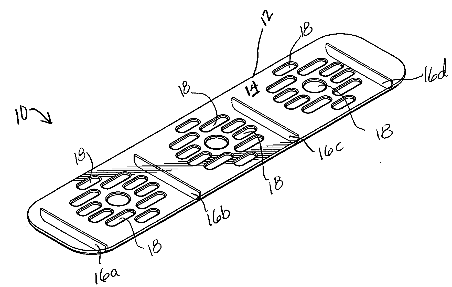
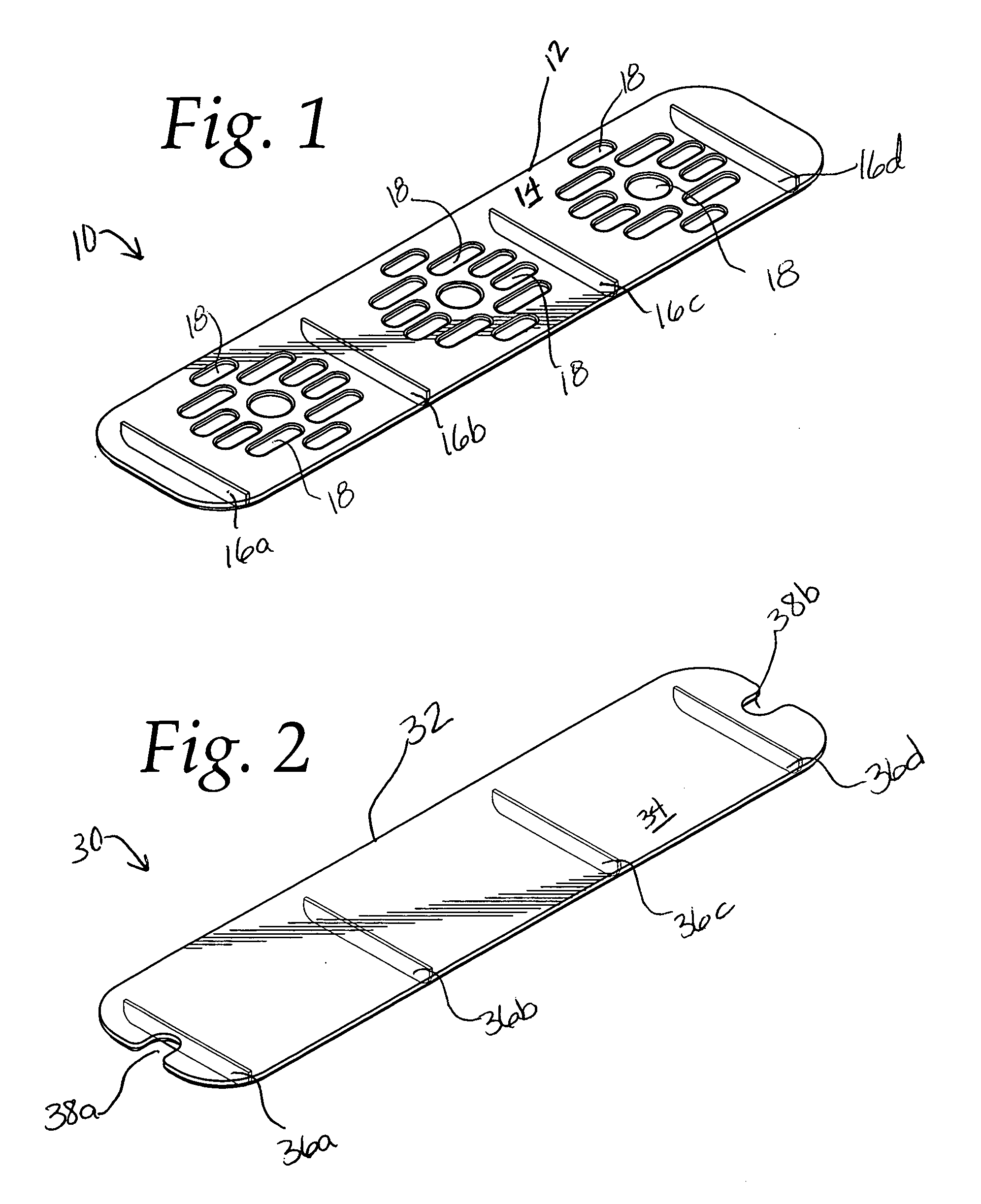
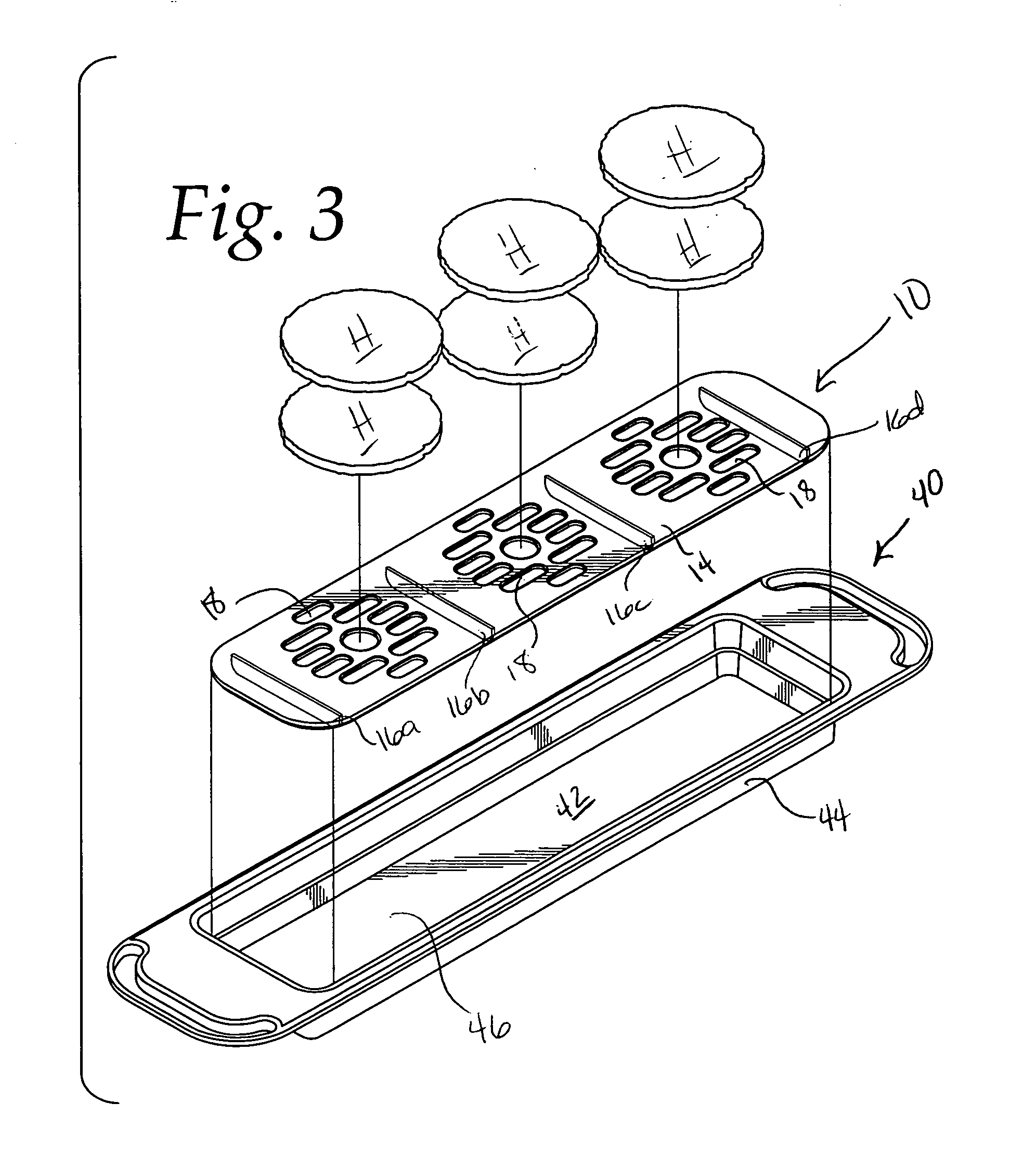
[0018]A food tray is provided which is adapted to store individual portions of food over
extended storage periods within a storage compartment. The food tray includes a tray body and a tray insert. The tray body includes a first end, a second end, a lower surface tray bottom, and a sidewall structure. The tray bottom and sidewall structure define a tray volume or cavity for the food tray within which a tray insert can be added and within which food product can be stored. The tray insert is positionable within the tray volume and includes an elongated supporting surface and insert supports. The supporting surface and insert supports define a tray insert height wherein the supporting surface is above the tray bottom lower surface and is below the top of the sidewall structure. The lower surface defines a volume between the lower surface and the supporting surface. The supporting surface defines a food holding volume in conjunction with the sidewall structure. Individual portions of food, such as hamburger patties, are placed on the supporting surface. The food tray having the individual portions of food stored therein is placed and stored for a period of time in a heated compartment having an upper compartment surface and a heated
lower compartment surface to maintain the temperature of the cooked
food products in a desired elevated storage temperature range, wherein the supporting surface is elevated above the heated
lower compartment surface. Typically, the cooked hamburger patties are maintained at a storage temperature of approximately 145° F. The food tray is maintained during storage so that the top edge of the tray is in close proximity to the upper compartment surface to achieve a gap between the top of the tray and the upper compartment surface of between about 0 and 0.25 inches to
restrict water vapor from evaporating from the cooked hamburger patties in the tray during storage in the compartment.
[0019]Preferably, the lower volume avoids significant
convection heat transfer between said heated lower compartment surface and said individual portions of food. Preferably, the gap is sufficiently sized to
restrict water vapor from evaporating from the cooked food in the tray during storage in the compartment.
[0022]In accordance with another aspect of the present invention, a method of making a hamburger sandwich is provided. A plurality of hamburger patties are cooked. A food tray is provided which is adapted to store individual portions of food over
extended storage periods within a storage compartment. The food tray includes a tray body and a tray insert. The tray body includes a first end, a second end, a lower surface tray bottom, and a sidewall structure. The tray bottom and sidewall structure define a tray volume or cavity for the food tray within which a tray insert can be added and within which food product can be stored. The tray insert is positionable within the tray volume and includes an elongated supporting surface and insert supports. The supporting surface and insert supports define a tray insert height wherein the supporting surface is above the tray bottom lower surface and is below the top of the sidewall structure. The lower surface defines a volume between the lower surface and the supporting surface. The supporting surface defines a food holding volume in conjunction with the sidewall structure. Individual portions of food, such as previously cooked hamburger patties are placed on the supporting surface. The food tray having the individual portions of food stored therein is placed and stored for a period of time into a heated compartment having an upper compartment surface and a heated lower compartment surface to maintain the temperature of the cooked
food products in a desired elevated storage temperature range, wherein the supporting surface is elevated above the heated lower compartment surface. Typically, the cooked hamburger patties are maintained at a storage temperature of approximately 145° F. The food tray is maintained during storage so that the top edge of the tray is in close proximity to the upper compartment surface to achieve a gap between the top of the tray and the upper compartment surface of between about 0 and 0.25 inches to restrict water vapor from evaporating from the cooked hamburger patties in the tray during storage in the compartment. Thereafter, the cooked hamburger patties are removed from the tray when needed for
assembly into hamburger sandwiches and the hamburger patties are assembled into hamburger sandwiches.


