
Multiple mode system with multiple controllers

a multi-mode system and controller technology, applied in the direction of electric programme control, program control, instruments, etc., can solve the problems of not being able to control the operation of the equipment in any way, unable to allow for any situations in which an operator can be present on or take over the operation of the equipment, and the reliability of unmanned equipment is not always high, so as to reduce the cost, avoid unnecessary duplication, and reduce the cost

Inactive Publication Date: 2007-12-20
DEERE & CO
View PDF29 Cites 42 Cited by
  • Summary
  • Abstract
  • Description
  • Claims
  • Application Information

AI Technical Summary

Benefits of technology

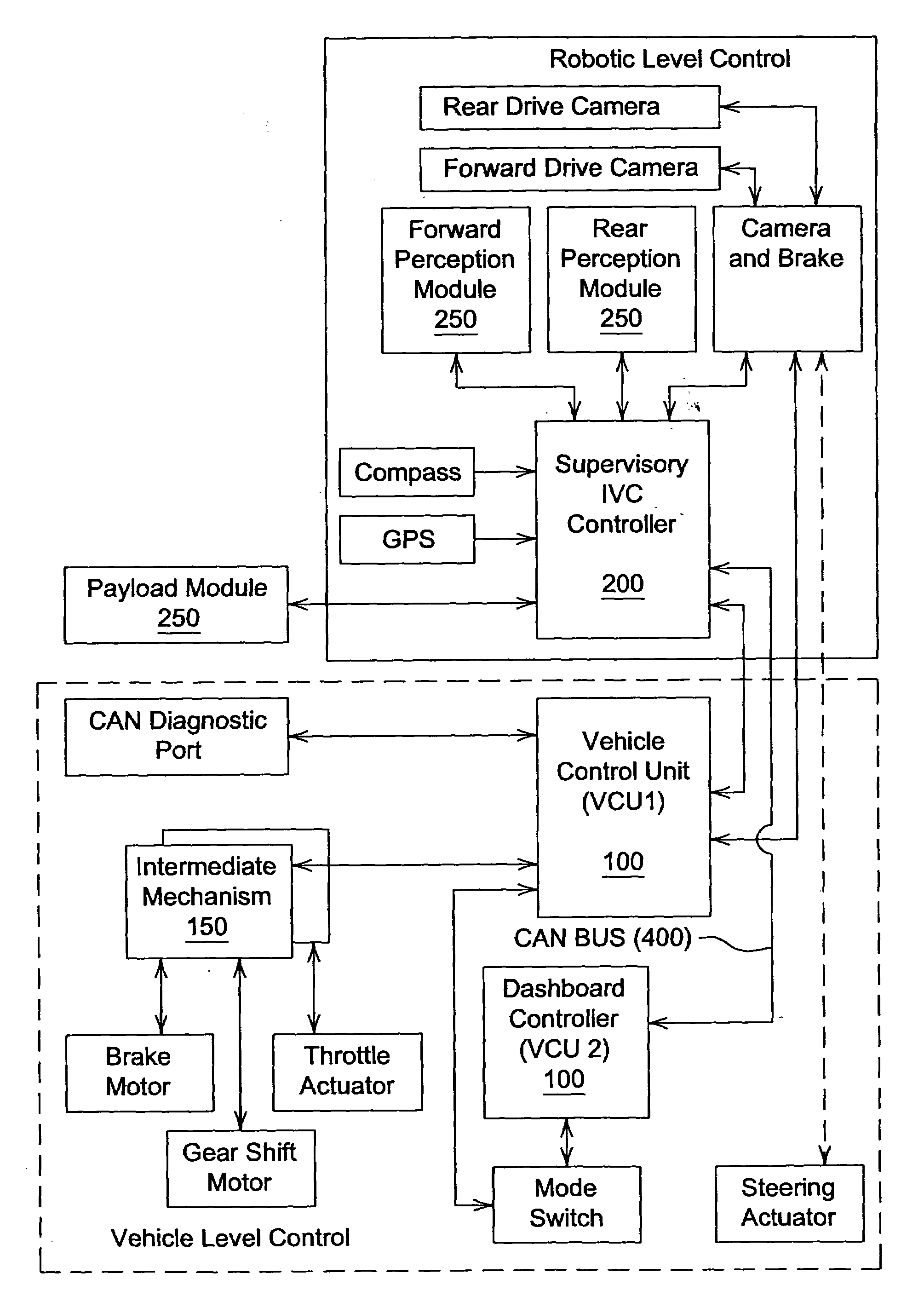
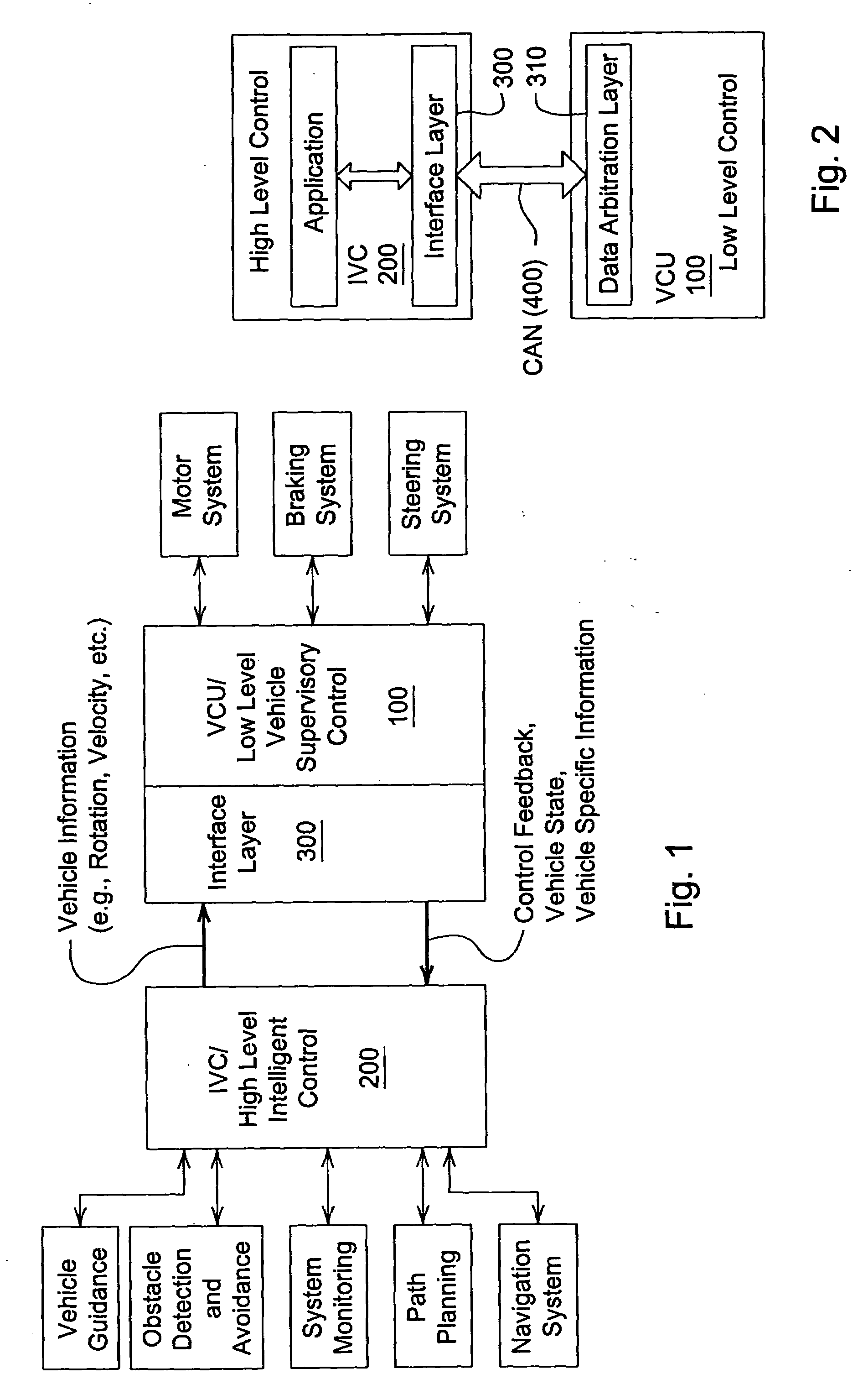
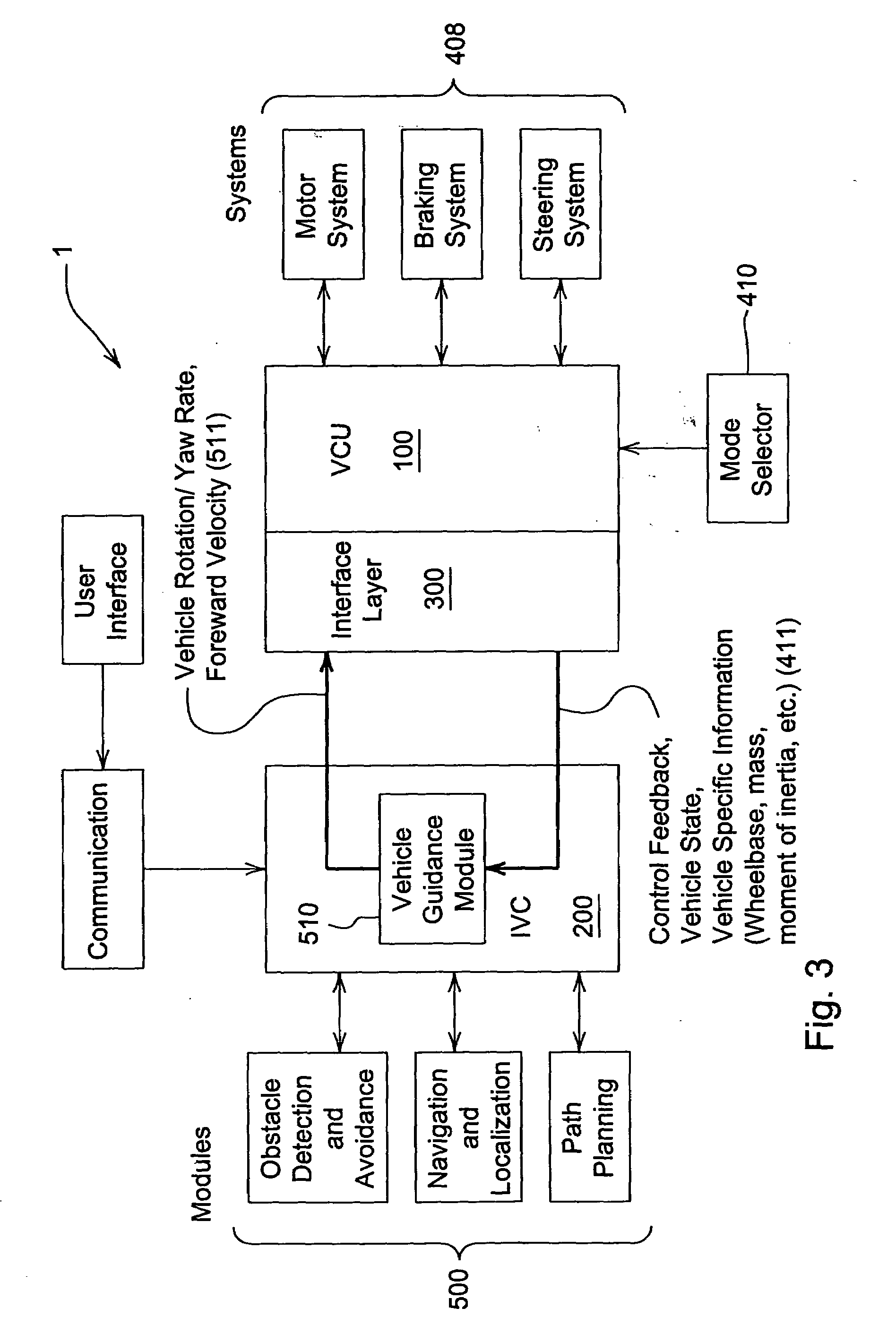
[0005]The present invention, accordingly, provides a method and system for both automated and manual control of mobile equipment, providing for the ability to manually control the equipment even when the automated control system experiences failures or faults. This is achieved by providing dual processors for controlling the system: one controller is a high-level, or automated controller, and the second controller, which is not just a redundant control system, is a low-level controller that serves as a supervisory controller for the equipment and performs equipment-specific control functions. In the event of a failure or fault in the high-level controller, or operations controlled by the high-level controller, or if fully manual control is implemented, the low-level controller can be used for manual operation of the equipment. By careful division of feature control into the high-level controller and low-level controller, avoidance of unnecessary duplication is achieved, reducing system cost. Such division can also enable using or reusing controller components in different equipment, or different types of equipment, thus reducing costs. Additionally, providing control of the automated functions in a separate controller can enable unmanned robotic equipment control to be an add-on feature, initially or at a later time.

Problems solved by technology

In some situations, these are completely different equipment from what were previously used, and do not allow for any situations in which an operator can be present on or take over operation of the equipment.
Such unmanned equipment is not always very reliable, based on the complexity of systems involved, the current status of computerized control, and uncertainty in various operating environments.
In such situations, depending on the failures that occur, the operator may have only limited ability to perform various actions.
In particular, the complex control systems required for automated operation cannot always be easily adapted to revert to operator-control.

Method used


Image

  • Multiple mode system with multiple controllers
  • Multiple mode system with multiple controllers
  • Multiple mode system with multiple controllers

Examples


Embodiment Construction

[0015]In the discussion of the FIGURES the same reference numerals will be used throughout to refer to the same or similar components. In the interest of conciseness, various other components known to the art, such as computer processing and storage mechanisms and the like necessary for the operation of the invention, have not been shown or discussed, or are shown in block form.

[0016]In the following, numerous specific details are set forth to provide a thorough understanding of the present invention. However, it will be obvious to those skilled in the art that the present invention may be practiced without such specific details. In other instances, well-known elements have been illustrated in schematic or block diagram form in order not to obscure the present invention in unnecessary detail. Additionally, for the most part, details concerning computer and database operation and the like have been omitted when such details are not considered necessary to obtain a complete understand...


PUM


Abstract

The present invention relates to a system and method for intelligent mobile vehicles that can be used in unmanned robotic or manned modes, the system having a plurality of controllers, with a low-level controller that controls basic operating functions for the mobile vehicles, and a high-level controller used to issue commands for unmanned robotic operation. Division of features between different controllers enables an ability to operate the mobile vehicle even if the high-level controller should fail or experience faults.

Description

FIELD OF THE INVENTION[0001]The present invention relates to a system and method for intelligent mobile equipment that can be used in unmanned or manned modes, the system having a plurality of controllers.BACKGROUND OF THE INVENTION[0002]There is an increasing trend towards automated or semi-automated equipment being developed for a variety of uses, rather than the operator-controlled equipment that was previously used. In some situations, these are completely different equipment from what were previously used, and do not allow for any situations in which an operator can be present on or take over operation of the equipment. Such unmanned equipment is not always very reliable, based on the complexity of systems involved, the current status of computerized control, and uncertainty in various operating environments. Therefore, what is more commonly seen is a piece of equipment similar to previous operator-controlled equipment that also incorporates one or more operations that are auto...

Claims


Application Information

Patent Timeline
IPC IPC(8): G06F19/00
CPCG05B9/03G05D1/0088Y02T10/7258G05D1/0259G05D1/0278G05D1/0246Y02T10/72
Inventor NORRIS, WILLIAM ROBERT
Owner DEERE & CO
Learn More