
In-line apparatus and real-time method to determine milk characteristics

a technology of in-line apparatus and real-time method, applied in the field of on-farm dairy milk analysis, can solve the problems of affecting the quality of milk, so as to achieve the effect of reducing the expense of the farmer in time and money

Inactive Publication Date: 2007-12-20
DAIRY CONTROLS INT
View PDF6 Cites 47 Cited by
  • Summary
  • Abstract
  • Description
  • Claims
  • Application Information

AI Technical Summary

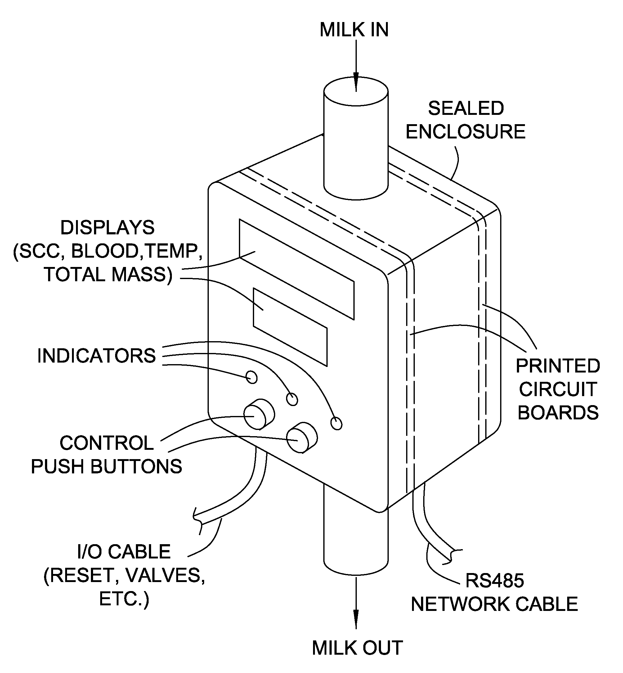
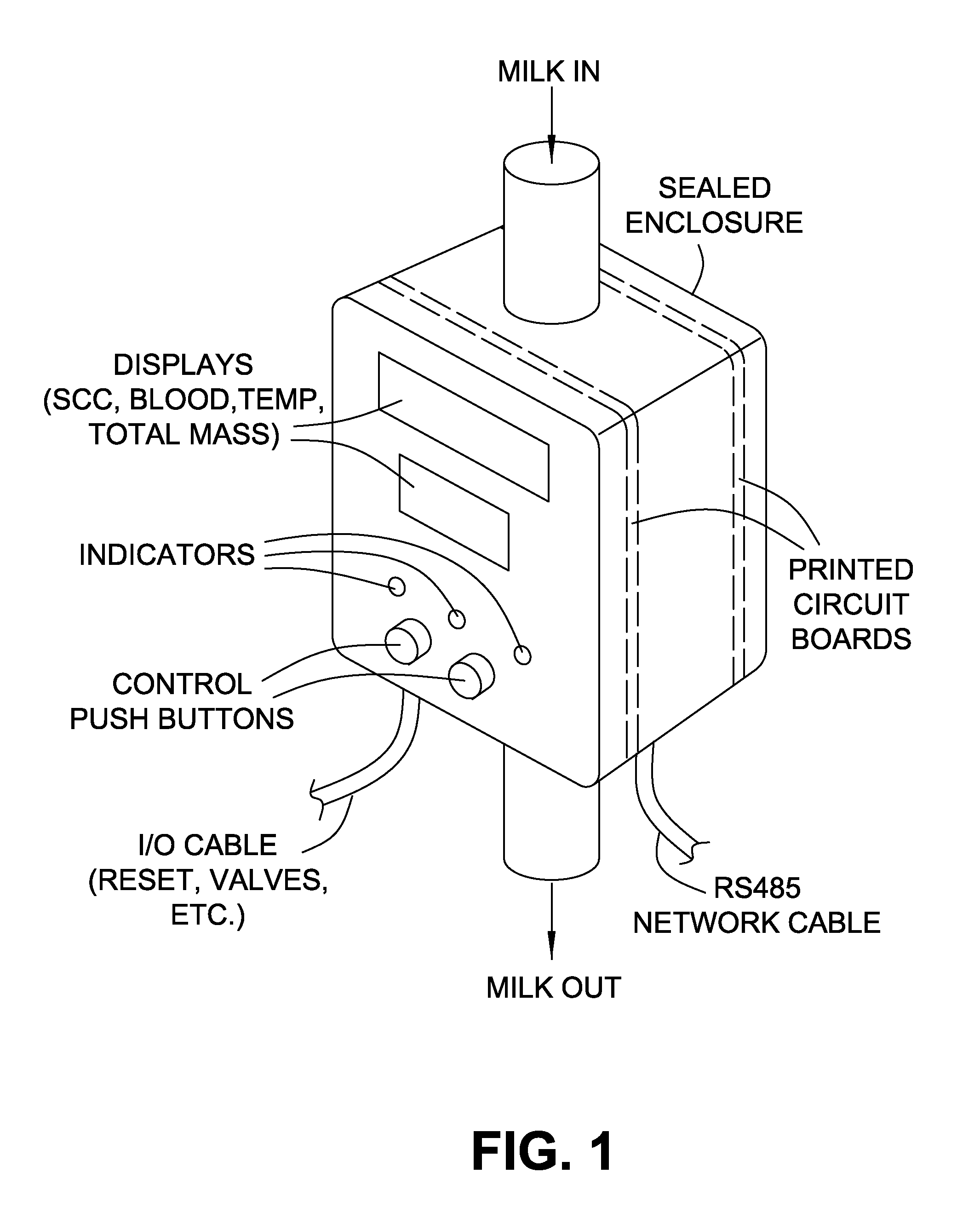
Benefits of technology

[0011]It is an object of the present invention to obviate or mitigate at least one disadvantage of previous dairy industry methods for milk analysis. The present invention provides great benefit to the milk industry in regard to test results indicating cleanliness and percentage of milk components, both on an individual animal basis and collectively. The present invention performs these tests while the milk is being obtained on the farm, resulting in advantageous reduction in expense to the farmer in terms of time and money.
[0012]The present invention seeks to provide for an apparatus used in the dairy industry that is robust, reliable, simple to install, small in size, cost effective, cleanable (using no more hot water or chemicals than to clean than milking pipe lines), low maintenance, and suitable for low line and high line systems. The present invention desirably includes a sealed apparatus that can be located vertically in-line without any moving parts. While vertical mounting is discussed, it should be understood that any other orientation such as horizontal mounting is possible without straying from the intended scope of the present invention. The present apparatus and associated method may be installed directly in-line with the milk collection apparatus for each animal so as to measure the entire milk yield produced by that animal at flow rates typically used in milking parlours, though requiring no unusual tube fittings or non-standard equipment. Such typical flow rates exist in a manner where there is a mixed flow of milk—i.e., a flow having mixed densities, air / liquid ratios, temperature variations, or any other similar variation of physical characteristics. While a mixed flow is discussed herein, it should further be understood that analyzing a more consistent flow may be possible where an upstream buffer can exist to ensure a filled tube where sensing occurs rather than partially or incompletely filled as in a mixed flow.
[0013]For purposes of describing the present invention, the terms milk yield and milking parlour are defined as follows. Milk yield is the volume of milk collected from a single animal during a single milking. Milking parlour is an array of milking equipment used to collect the milk from several animals simultaneously and combine the resultant milk flows into a tube leading to a reservoir for subsequent transport to a milk food processing facility. It should be understood that the term milking includes collecting the milk from all available animals. It should further be understood that a cleaning, or flushing, of the system would of course be desirable so as to enhance the veracity of analysis.

Problems solved by technology

For the lack of technological know-how, these evaluations are performed off the farm at great expense to the farmer in terms of time and money.
In many cases however, animals with significant levels of foreign bodies in their milk such as blood or so-called mastitis flakes, present no external symptoms as the disease or injury has not yet advanced to that degree.
Dairy installations such as milking parlours often combine the milk collected from several animals into a single, main stream providing the risk for contamination of a large volume of high quality milk by the milk collected from a single injured or infected animal.
This is undesirable as it results in contamination of the milk with the foreign substance in question and requires that a consumable indicator be available whenever a measurement is required.
However, the trend to use more automation, particularly milking robots, is impeded by the requirement that cows be inspected for mastitis visually by an operator.
Attempts to reduce the costs of known methods have been limited to conventional means such as test process automation.
To date, no prior art exists for the direct measurement of foreign body size in a milking parlour system, or for the potential to collect a large number of samples data points for each milk yield.
Moreover, no prior art exists for detecting foreign bodies or disease indicators in milk without diverting a portion of the milk from the main flow of the yield.
Current methods for detection of infections in milk are therefore limited.
Moreover, response times for the detection of infections in milk within current methods can be 45 seconds or more, which is inadequate to allow timely decisions on diversion of the yield from an injured or infected animal to waste, or to dilution in the rest of the milk volume from the healthy animals, etc.
Using current methods, it is not readily possible to reduce the cost of prior art instruments to the level that would permit the detection of indicators of disease such as mastitis at every milking station in a significant proportion of all milking parlours.
Known mastitis detection methods and instruments have not addressed the intrinsic problems of contamination and sampling, relying as they do on the use of consumable materials.
Such known methods provide neither a direct measure of foreign body size nor the potential to collect a large number of samples owing to the inherently long response time.

Method used


Image

  • In-line apparatus and real-time method to determine milk characteristics
  • In-line apparatus and real-time method to determine milk characteristics
  • In-line apparatus and real-time method to determine milk characteristics

Examples


second embodiment

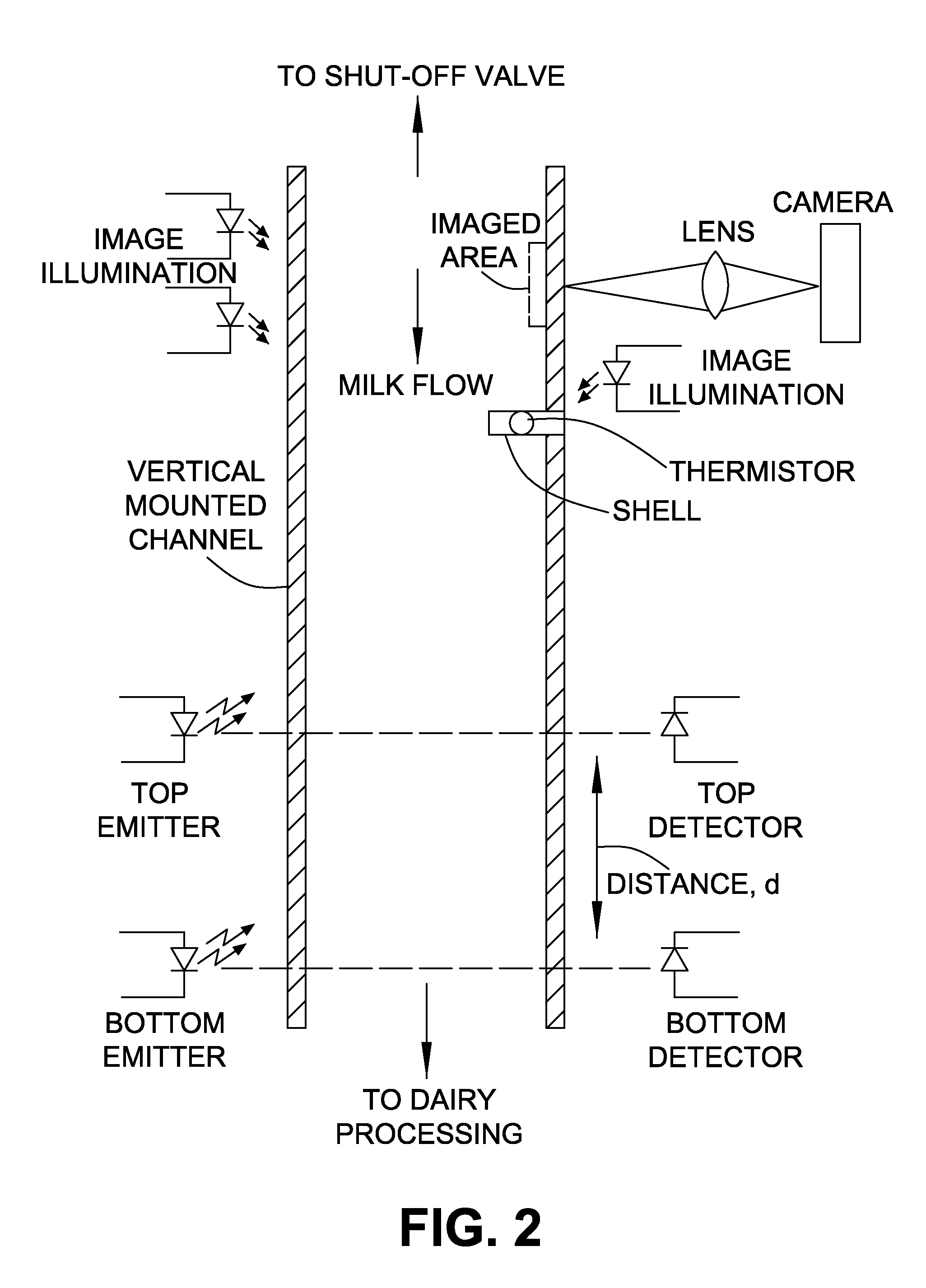
[0069]these techniques also includes the use of one or more electronic cameras to capture images of the milk flow thickness against one or more tube or conduit surfaces of known profile, e.g., a flat plane. The position of features in the fluid flow in successive images may be measured by counting the number of pixels between the positions in the successive images and applying the known magnification factor. The elapsed time between images is known and hence the velocity may be estimated.

first embodiment

[0070]In a design such as the first embodiment above, the camera will deliver a video signal for processing in which the image sequence is continuous, that is there are no gaps between images corresponding to time periods when the fluid was flowing but no image was captured. In practice, the signal processing power and expense required to continuously analyze video images to measure the flow velocity is currently difficult to realize and also too expensive for an instrument that is to be installed at every milking station. There are several methods that may be applied to address this practical problem.

[0071]In one method, it is sufficient to apply the processing power of a single processor and associated hardware and software that is affordable to successive pairs of images, and use an averaging function to estimate the flow velocity for the time period between measurements when the processor is analyzing the preceding image pair. The sequence of events includes: the capture of a fi...


PUM


Abstract

An apparatus and related methods using photographic imaging and the interactions between light beams and dairy milk to provide in-line monitoring, analysis, and display of the quality of milk collected from dairy animals. The apparatus is robust in that it is reliable, simple to install, relatively small in size, cost effective, easily cleaned, and low maintenance. The apparatus can be installed directly in-line with the milk collection apparatus for each animal so as to measure the entire milk yield produced by that animal at flow rates typically used in milking parlours without requiring any unusual tube fittings or non-standard equipment. The apparatus is capable of handling analysis of a flow having mixed densities, air / liquid ratios, temperature variations, or any other similar variation of physical characteristics.

Description

CROSS-REFERENCE TO RELATED APPLICATIONS[0001]This application claims the benefit of priority of U.S. Provisional Patent Application No. 60 / 812,108 entitled “In-Line Apparatus and Real-Time Method to Determine Milk Characteristics” filed Jun. 9, 2006, the contents of which are entirely incorporated herein by reference.FIELD OF THE INVENTION[0002]The present invention relates generally to on-farm dairy milk analysis. More particularly, the present invention relates to a method and apparatus for in-line monitoring, analysis, and display of the quality of milk collected from dairy animals (cows, goats, sheep, etc.) during the milking process usingBACKGROUND OF THE INVENTION[0003]In the field of dairy farming, milk quality is a constant concern. The industry partners and consumers demand high quality milk free from contamination. Milk pricing is based on test results indicating cleanliness and percentage of components, both on an individual animal basis and collectively. For the lack of ...

Claims


Application Information

Patent Timeline
Patent Type & Authority Applications(United States)
IPC IPC(8): A01J5/01
CPCA01J5/01A01J5/0138A01J5/0135A01J5/0132
Inventor DUNN, JAMESDUTRA, RENATOWADE, JOHNMANGAN, STEVEN
Owner DAIRY CONTROLS INT
Learn More