
Nestable, rigid, planar air filter frame

Inactive Publication Date: 2007-12-20
FLANDERS FILTERS
View PDF18 Cites 21 Cited by
  • Summary
  • Abstract
  • Description
  • Claims
  • Application Information

AI Technical Summary

Benefits of technology

[0024]The present invention is directed to a planar, nestable air filter with several variations in frame geometry capable of providing a simple, stable frame for planar air filter panels. The frame design described is cost-effective in manufacturing and operation, and allows for savings in storage, transportation, material handling labor, and packaging costs, since the volume is reduced significantly when several air filters are packaged together. In addition, the frame geometry including a simple, structurally enclosed void, provides sufficient rigidity to result in a high-quality filter.
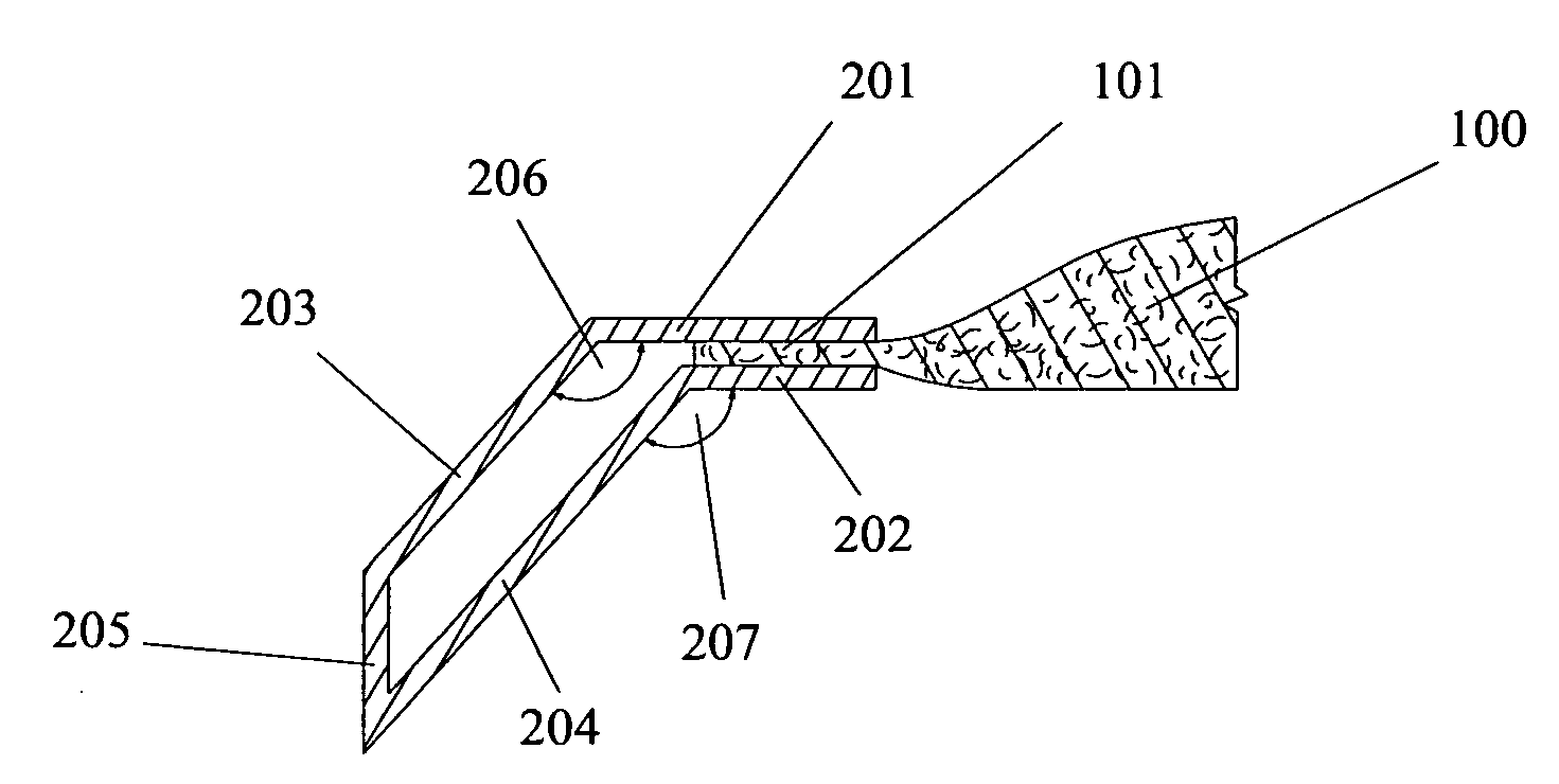
[0026]The angles between the first and the second legs of both the upper and lower frame portions are obtuse. This is significantly different from prior art and important, because it allows for nesting of the filter frames. Furthermore, the angle of the lower frame portion is always equal or larger than the angle of the upper frame portion. This is significantly different from prior art and important, because it increases the rigidity of the frame specifically and effectively at the connection point between the first and the second legs of the frame portions, which is most important for overall frame stability.

Problems solved by technology

None of the prior art provide a frame with all of the following desirable properties: 1) simple manufacturing and assembly process, 2) simple design, 3) enhanced structural rigidity, 4) significant space-savings during storage and transport, 5) simple handling, and 6) lower material handling and packaging costs.
Filter frames in prior art that provide for sufficient frame stability contain tubular profiles or voids that make the frame complex and difficult to manufacture.
Filter frames in prior art with only one frame leg extending from the planar filter media are simple in design but do not provide sufficient rigidity.
Filter frames that can be stacked tightly in a collapsed mode, and become rigid by unfolding them to the operating mode, require additional attention after packaging and transport, and therefor increase operating cost.

Method used


Image

  • Nestable, rigid, planar air filter frame
  • Nestable, rigid, planar air filter frame
  • Nestable, rigid, planar air filter frame

Examples


Embodiment Construction

[0033]In the following description, like reference characters designate like or corresponding parts throughout the several views. Also in the following description, it is to be understood that such terms as “forward,”“rearward,”“front,”“back,”“right,”“left,”“upwardly,”“downwardly,”“horizontal,”“vertical,” and the like are words of convenience and are not to be construed as limiting terms.

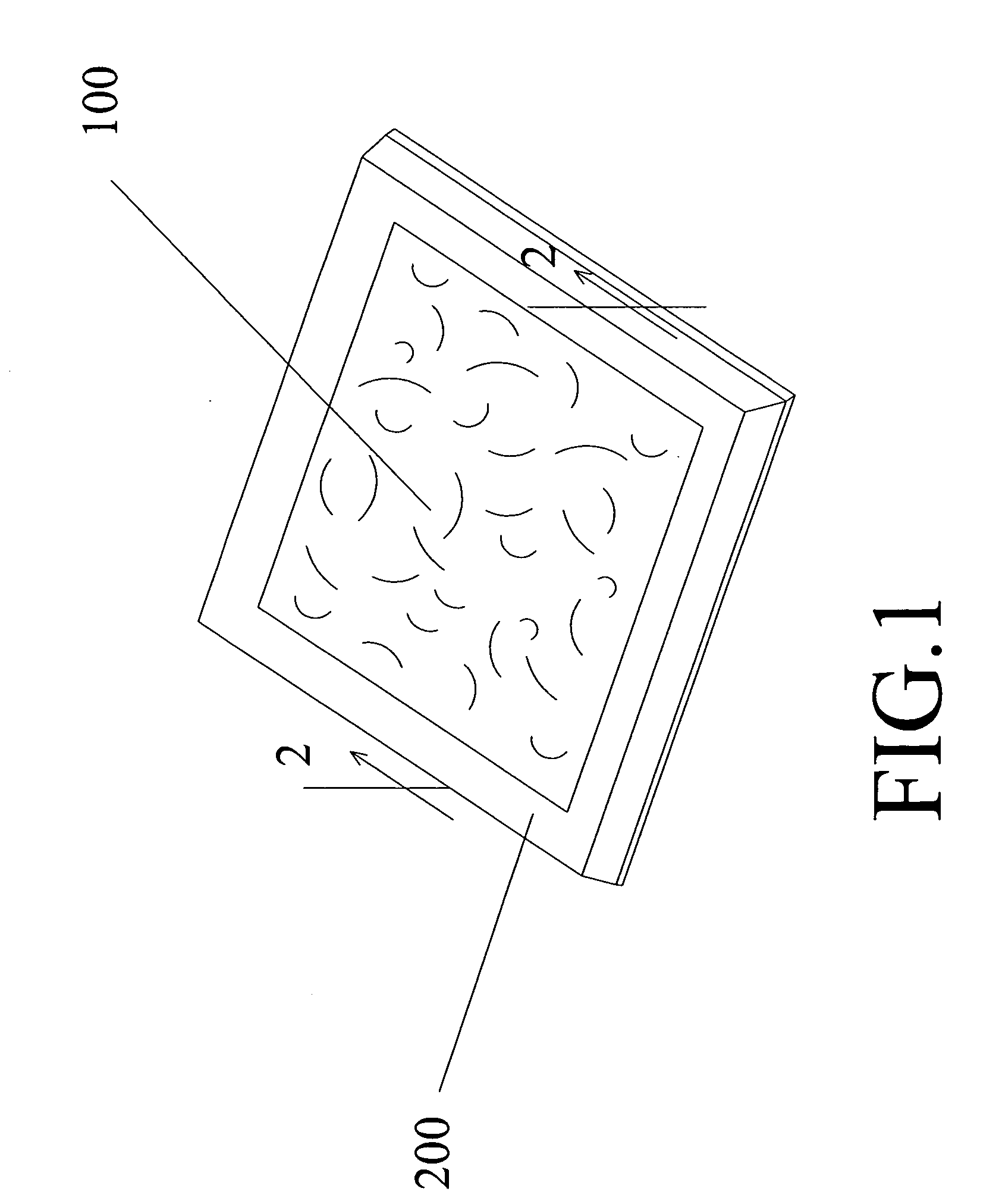
[0034]Referring now to the drawings in general, the illustrations are for the purpose of describing a preferred embodiment of the invention and are not intended to limit the invention thereto.

[0035]FIG. 1 shows a perspective illustration of the filter. The filter comprises a planar panel of filter medium, 100, which is delimited to all sides by the surrounding periphery 101. The surrounding periphery of the filter medium is held within the filter frame 200. Preferably, the frame member may be made of cardboard. Alternatively, the frame member could be made of thermoformed polystyrene, PVC, paperboar...


PUM

PropertyMeasurementUnit
Angleaaaaaaaaaa
Stiffnessaaaaaaaaaa

Abstract

A nestable frame for planar air filters or other screen-like planar structures.The nestable frame provides all of the following desirable properties at once: 1. Simple manufacturing and assembly process, 2. Simple design, 3. Enhanced structural rigidity, 4. Significant space-savings during storage and transport, and 5. Simple handling.The filter frame comprises an upper and a lower frame portion with a first leg each, where the peripheral edge of the filter media is clampingly engaged between the first leg of the upper frame portion and the first leg of the lower frame portion. From the first leg, both frame portions extend outwardly with a second leg at an obtuse angle. The frame portions are connected at the outer ends of their second legs with a connecting leg. Alternative embodiments contain straight connection legs at different angles, curved connection legs or a multitude of connection legs, oriented to the outside of the frame or collapsed inwardly into the frame, for various purposes.Yet alternative embodiments include various values for the obtuse angles between the first and second legs of the upper and lower frame portion. While same angles between corresponding legs of both frame portions may allow for easier design of the frame, a larger angle in the lower frame portion may allow for greater rigidity of the frame at the level of the plane of the filter medium.

Description

BACKGROUND OF THE INVENTION[0001]1. Field of the Invention[0002]The present invention relates generally to air filters and, more particularly, to a nestable frame for planar air filters or other screen-like planar structures.[0003]2. Description of the Prior Art[0004]Filters are typically provided in heating, ventilating and air conditioning equipment upstream of the air handler for removing particulate impurities from the air principally in order to protect the equipment, and secondarily to remove particulate impurities from the air circulated within homes, offices and industrial environments that affect the indoor air quality to which people are exposed. Such filters are also used for removing impurities entrained in air or another gas prior to release of the gas into the atmosphere. Various industrial processes also use filters for removing particulates from gases or other fluids.[0005]Filters are typically formed by mounting a panel of a filter medium, such as a fibrous mat or p...

Claims


Application Information

Patent Timeline
IPC IPC(8): B01D46/00
CPCB01D46/0002B01D46/10B01D46/0013
Inventor JUSTICE, THOMSA A.MERCER, JAMES B.
Owner FLANDERS FILTERS
Learn More