
Wireless base station device

a base station and wireless technology, applied in power management, data switching networks, instruments, etc., can solve the problems of difficult to prepare suitable parameters in advance, inability to perform proper operations, and easy damage to cells

Inactive Publication Date: 2007-12-13
KOKUSA ELECTRIC CO LTD
View PDF7 Cites 145 Cited by
  • Summary
  • Abstract
  • Description
  • Claims
  • Application Information

AI Technical Summary

Benefits of technology

[0032]To solve the above problems, it is a first object of the present invention to provide a wireless base station device of a small-scale area configuration to be installed by a user as desired, which can automatically execute settings of a spreading code or a transmission power required for the installation of the base station device itself. This is implemented by, at a start-up of the device, converting a baseband signal processing into a downlink signal reception of other base station devices and finding out notification information or signal levels of neighboring base station devices of wireless access type to thereby detect installation conditions and radio wave propagation conditions of the neighboring base station devices that are dependent on the installation place of the wireless base station device.

Problems solved by technology

In this case, cells tend to be easily affected by, e.g., landforms, structures such as buildings, or external interferences with neighboring cells.
However, if a place at which the base station device is to be installed is not specified in advance, when the operation is started by installing the base station so that a degree of freedom is given with regard to the installation place, it is difficult to prepare suitable parameters in advance.
Especially in a case where a relatively small number of terminal devices are acceptable to the base station device and the base station device is small in size, if predetermined initial parameters are applied without considering the environment depending on the place to be used, there are many cases where proper operations are not possible due to the effects of, e.g., interferences in communications between the base station device and terminal devices and those between neighboring base station devices and terminal devices.
However, if, for example, a scramble code number of the base station device to be installed is same as that of a neighboring base station device, an identification of cell is not possible.
In this case, if a set power level is not suitable for an area covered by the base station device, interferences take place to affect terminal devices that are communicating with neighboring base station devices to thereby deteriorate a communications quality.
However, if a different frequency is arbitrarily assigned, and a target base station device to which a handover is expected cannot accept the different frequency that has been arbitrarily assigned, a forced release is carried out to thereby increase a call loss probability.
Moreover, since a hard handover is used for transferring a call between cells using different frequencies, a diversity effect, that can be obtained in case of transferring a call between cells using a same frequency by a soft handover, cannot be obtained.
Thus, since the wireless base station setting device disclosed in Patent Document 1 does not search neighboring base station devices for itself, it is not possible to obtain information of an actual environment in which the wireless base station device is installed.
However, since the wireless base station device is configured such that the area configuration is set by a user, it is difficult to perform an optimal area configuration in which communications overheads or interferences with other base station devices are taken into consideration.
In this case, it is also supposed that many workers are required, which need immense installation expense.
In addition, since the communication area of each base station device is small, it would be quite difficult to install a plurality of base station devices in order to prevent any leakage in such communication area.
However, it is problematic that the communication provider does not usually teach setting data of the base station device to common users.

Method used


Image

  • Wireless base station device
  • Wireless base station device
  • Wireless base station device

Examples


first embodiment

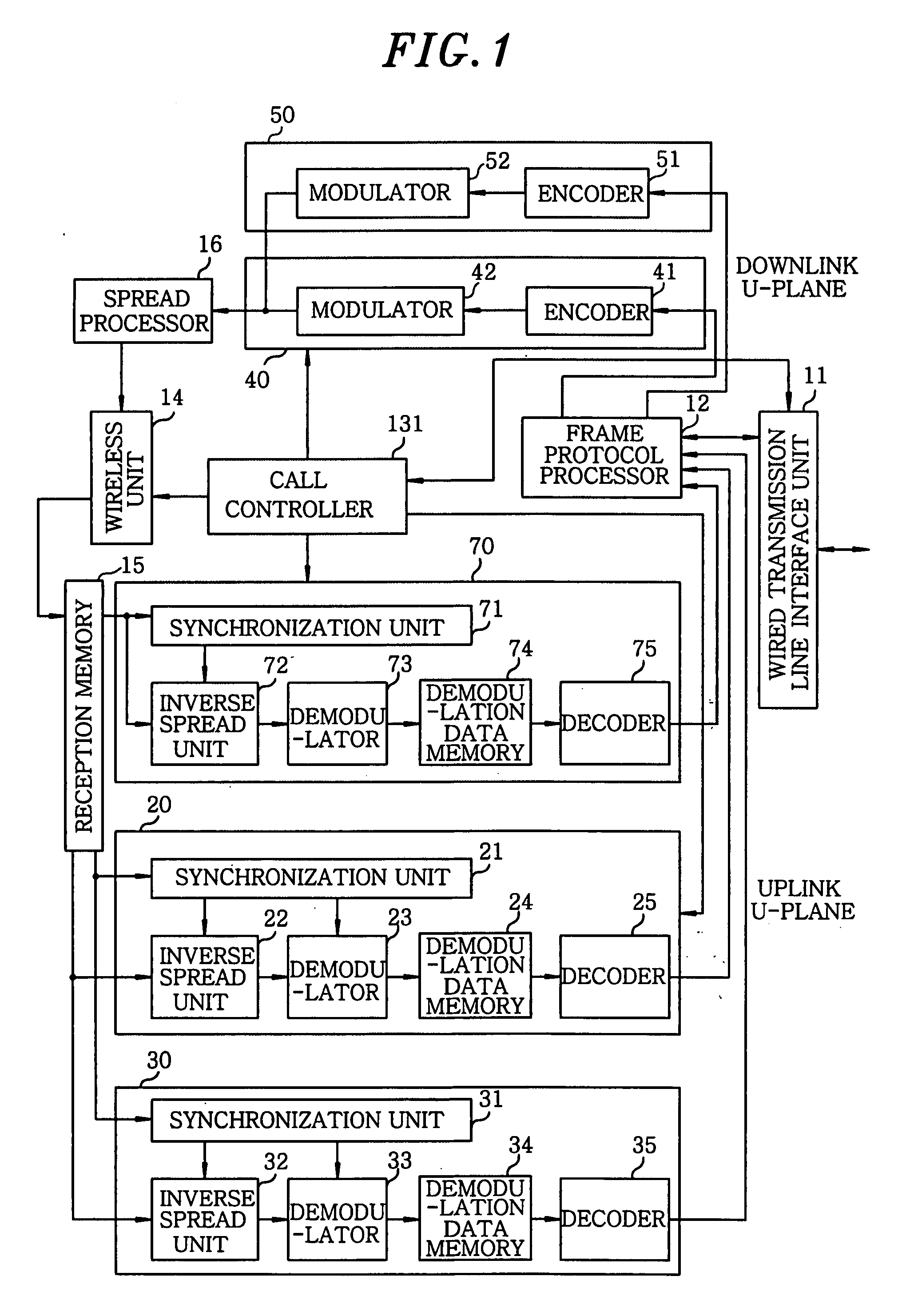
[0081]Hereinafter, a first embodiment of the present invention will be described in more detail with reference to the accompanying drawings. Hereinafter, same reference numerals are denoted for same parts as in the conventional device shown in FIG. 4.

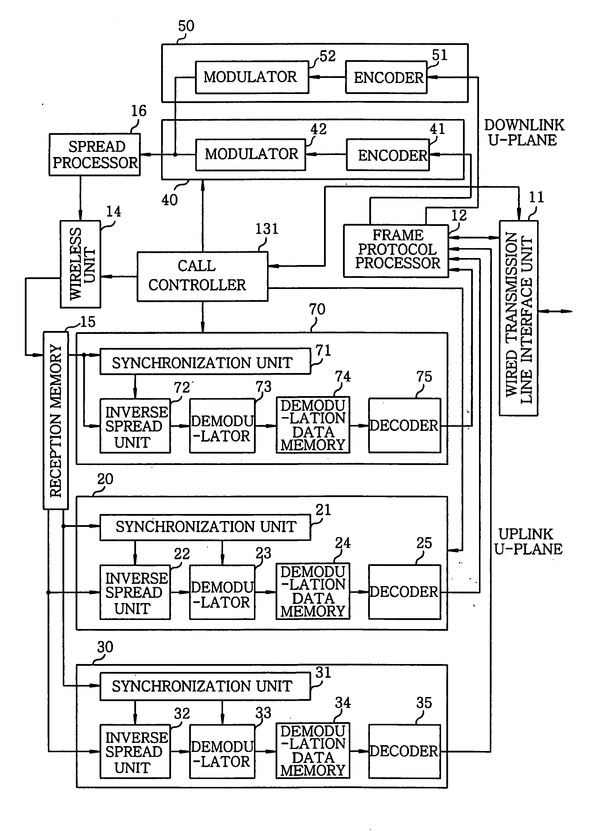
[0082]FIG. 1 shows a block diagram illustrating an exemplary configuration of a baseband unit of a wireless base station device in accordance with a first embodiment of the present invention. The wireless base station device includes a wired transmission line interface (IF) unit 11 connected to an upper-level device (RNC); a frame protocol (FP) processor 12 for performing a frame protocol processing required for interfacing with the wired transmission line; a call controller 131 for performing a call control; a wireless unit 14 for communicating with a mobile station; a reception memory 15 for storing sampling data of uplink reception data outputted from the wireless unit 14; a baseband receiver 20 of an individual uplink channel for pe...

second embodiment

[0129]Hereinafter, a second embodiment of the present invention will be described in detail with reference to the accompanying drawings.

[0130]FIG. 6 is a diagram illustrating an exemplary configuration of a wireless communications system in accordance with a second embodiment of the present invention.

[0131]The wireless communications system of the second embodiment includes a terminal device 611, a base station device (radio base station device) 601, a router 602, a modem 603, a network 604 comprised of a telephone line, an optical fiber and the like, a circuit-terminal equipment 605, a server 606, a gateway 607, and a base station controller (radio base station controller) 608.

[0132]Here, this embodiment illustrates a case of using PPPoE, wherein the base station device 601 is equipped with a PPPoE client function and the server 606 is equipped with a PPPoE server function. Further, the router 602 has a PPPoE pass-through function, and the base station device 601 and the router 602...


PUM


Abstract

A wireless base station device includes a wireless unit for performing wireless communications with a mobile station; a reception memory unit for storing therein reception spectrum spread data as reception data; a baseband reception unit for processing and decoding the reception data stored in the reception memory unit; a common downlink channel reception unit for receiving a downlink signal of other base station devices; a frame protocol processing unit for converting a transmission channel format; a baseband transmission unit for outputting encoded data; a spread processing unit for outputting spread-modulated data to the wireless unit; and a call controller for controlling an allocation of processing resources. Parameters including a spreading code and a transmission power required for installing the wireless base station device are automatically set by operating the common downlink channel reception unit to detect notification information and signal levels of neighboring base station devices.

Description

FIELD OF THE INVENTION[0001]The present invention relates to a wireless base station device using, e.g., a CDMA (Code Division Multiple Access) wireless communications system.BACKGROUND OF THE INVENTION[0002]Conventionally, a wireless base station device using a wireless communications system of a CDMA scheme performs controls thereof as described below. In wireless base station devices of a same wireless access scheme, based on conditions such as channel capacities and transmission power levels of the respective base station devices, various kinds of area configurations are considered to be applied to a service area covered by each base station device. To be more specific, in case where a wireless base station device is installed, it is required that, by surveying specific environmental conditions of an installation place, an area configuration be set based on an arrangement design of the base station device in order to avoid interferences with other base station devices.[0003]Spec...

Claims


Application Information

Patent Timeline
IPC IPC(8): H04M1/00
CPCH04W16/02H04W88/08H04W84/045H04W52/367
Inventor HOSHINA, KOYAKIMOTO, YUKINAO
Owner KOKUSA ELECTRIC CO LTD
Learn More