
Compact test apparatus for hearing device

Inactive Publication Date: 2007-12-13
SIEMENS AUDIOLOGISCHE TECHN
View PDF3 Cites 92 Cited by
  • Summary
  • Abstract
  • Description
  • Claims
  • Application Information

AI Technical Summary

Benefits of technology

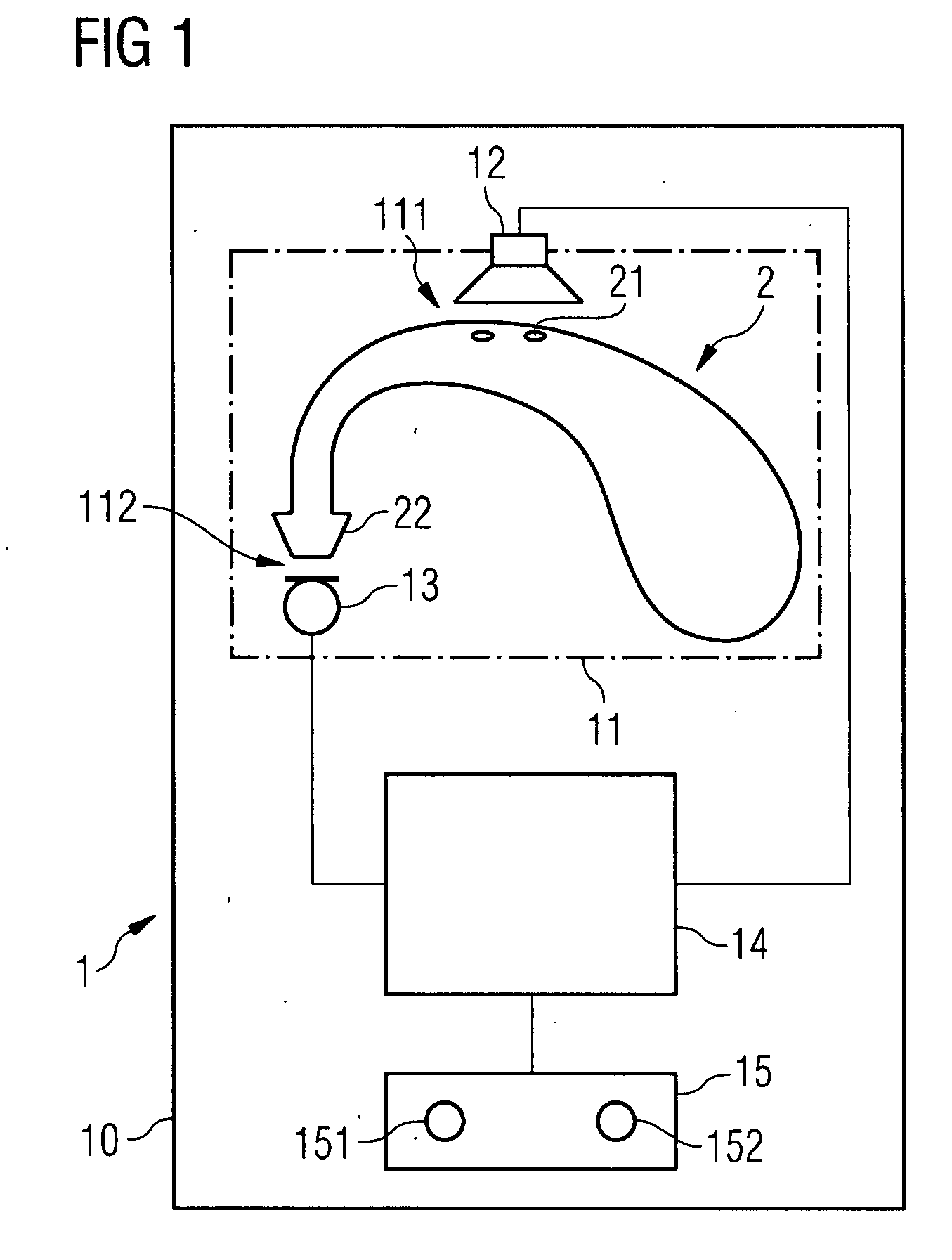
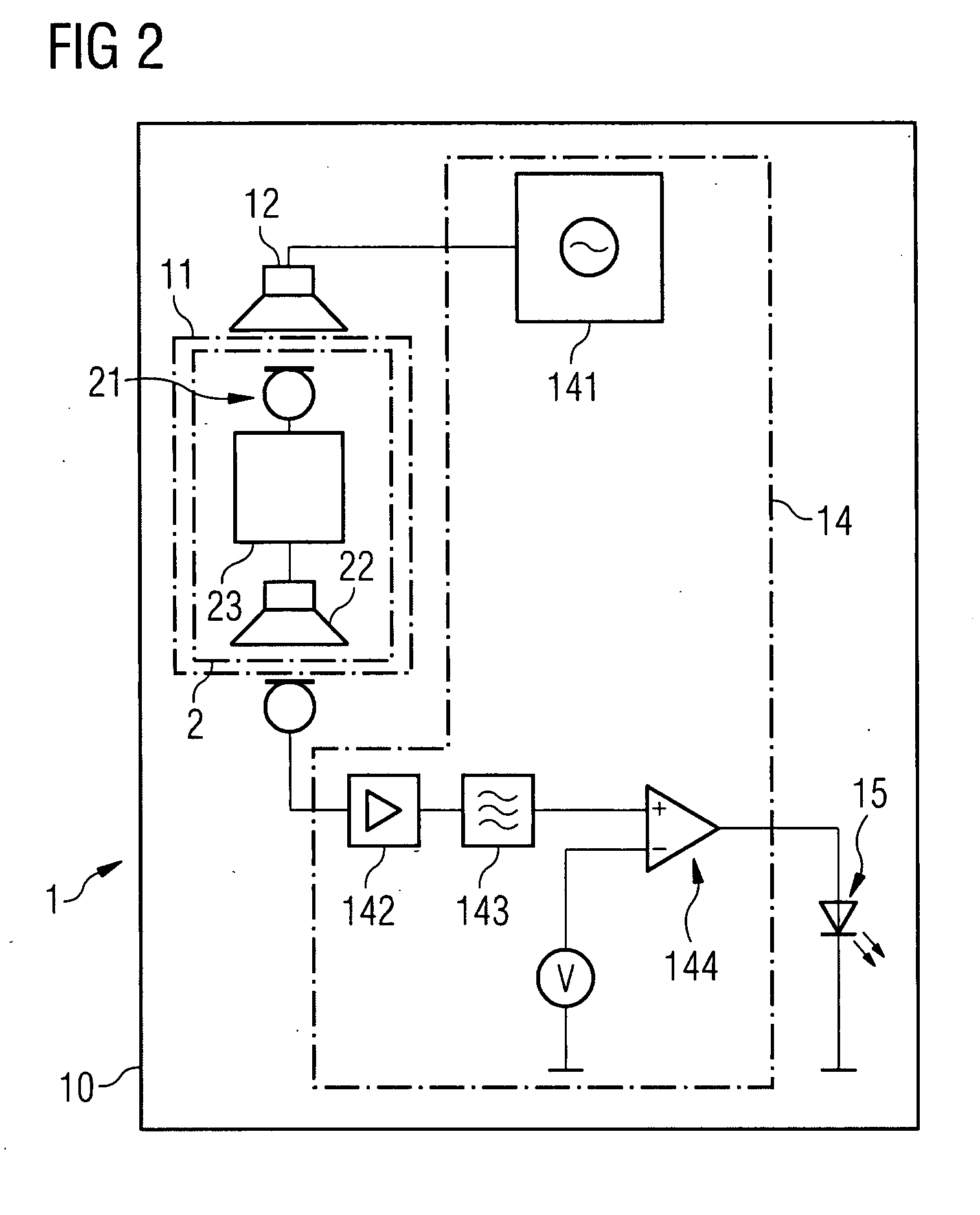
[0014]In accordance with the invention, a device for testing a hearing device is provided featuring a housing with a test area for accommodating a hearing device, with the test area including a microphone area and an earpiece area. Furthermore a signal generator and a loudspeaker are provided in order to create a defined acoustic test signal in the microphone area. In addition a microphone is arranged in the earpiece area, in order to detect an acoustic response signal output by the hearing device. An evaluation circuit is provided to assess the functional state of the hearing device on the basis of the response signal. The functional state of the hearing device is finally displayed on a display device. With the aid of the test apparatus the functional state can be objectively assessed very simply and automatically.
[0015]In an advantageous embodiment of the invention the display device is embodied to display the functional state optically and / or acoustically. The optical display in particular allows the test result to be easily checked.
[0017]In an especially advantageous embodiment of the invention there is provision for a green light emitting diode to be used as the first light source and for a red light emitting diode to be used as second light source. Since the significance of these colors is generally known, the operation of the device can be simplified in this way.
[0020]In a further advantageous embodiment of the invention the evaluation circuit assesses the functional state of the hearing device on the basis of a comparison between the test signal and the response signal. This allows undesired deviations in the signal processing of the hearing device to be detected particularly easily.
[0021]An advantageous embodiment of the invention provides for the earpiece area and the microphone area to be acoustically screened from each other. Disturbing feedback is avoided in this way and thereby a more precise measurement made possible. It is advantageous in this case to model the earpiece area on the earpiece of the hearing device in order to accommodate the earpiece using a positive and / or non-positive fit and thus screen it acoustically from the microphone area.

Problems solved by technology

Furthermore the hearing devices must be maintained and looked after in day-to-day use service by their wearers, since the hearing device adjusted on the basis of an individual audiogram can be affected by different factors, such as dirt or damage for example.
As a result of this the sound of the hearing device can be distorted, noisy or disturbed in some other way.
In particular contamination of the hearing device, e.g. sweat or the cerumen to be found especially in the outer auditory canal, can reduce the sound quality of the hearing device.
Such contamination is above all critical at the microphone openings since it can frequently not be detected by a simple visual inspection.
The distortions arising from these causes can also often not be perceived by those affected, especially when they occur progressively and, because of the subjective perception of those involved, are not appropriate for producing the feeling of a deterioration in sound.
Small children in particular are frequently not able to establish malfunctions or distorted reproduction of the hearing device themselves and rectify it where necessary.
An assessment of the function of the hearing device by means of a stethoclip is however very subjective.
This all demands specific knowledge and abilities, making the test system not suitable for all users.
The device merely serves to demonstrate different hearing devices and their transmission characteristics and because of its embodiment is not suitable for testing a hearing device.
Since the test apparatus uses facilities such as a computer, a certain level of knowledge and ability is required to use it, which once again greatly restricts the applicability of the test apparatus.

Method used


Image

  • Compact test apparatus for hearing device
  • Compact test apparatus for hearing device
  • Compact test apparatus for hearing device

Examples


Embodiment Construction

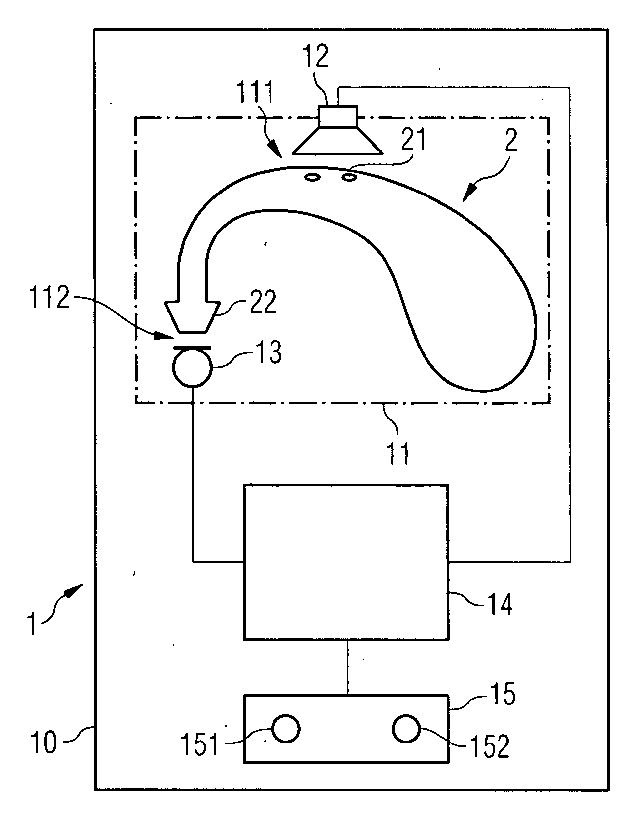
[0029]FIG. 1 shows an example of an inventive test apparatus 1 with a hearing device 2 arranged in it. Preferably this test apparatus 1 is embodied as a compact pocketable unit in the form of a simple test box so that users can always carry it with them. The housing 10 of the test apparatus features an area to accommodate a hearing device 2, referred to below as the test area 11. This test area 11 can be specifically adapted to accommodate a particular hearing device. Preferably the accommodation area 11 features special cutout shapes which correspond to the relevant hearing device 2. To fix the hearing device 2 in a predetermined position in the test apparatus 1 further retaining devices can be provided (not shown here).

[0030]The test area 11, only shown by a dashed line in FIG. 1, includes a microphone area 111 and an earpiece area 112. These areas are preferably arranged so that, when a corresponding hearing device 2 is placed in the holder, the hearing device microphone 21 lies ...


PUM


Abstract

An apparatus for testing of a hearing device is described, which includes the following components:a housing with a test area embodied to accommodate a hearing device, with the test area including a microphone area and an earpiece area,a signal generator and a loudspeaker, to create a defined acoustic test signal in the microphone area,a microphone arranged in the earpiece area to detect an acoustic response signal emitted by the hearing device,an evaluation circuit to assess the functional state of the hearing device on the basis of the response signal, anda display device to display the functional state of the hearing device.

Description

CROSS REFERENCE TO RELATED APPLICATIONS[0001]This application claims priority of German application No. 10 2006 026 721.4 DE filed Jun. 8, 2006, which is incorporated by reference herein in its entirety.FIELD OF INVENTION[0002]Hearing devices serve to restore or improve the hearing capabilities of those with impaired hearing. Different types of hearing device are employed in such cases.BACKGROUND OF INVENTION[0003]The most widespread are the so-called BTE (behind-the-ear) devices which are worn behind the ear. They are suitable for almost all types of hearing impairment. In addition there are ITE (in-the-ear) devices as well hearing aid eyeglasses. Apart from their different external embodiments, all hearing devices typically feature the same technical components, namely a microphone, an earpiece, an amplifier circuit and also a battery. In addition specific circuits such as filter circuits are used, with the aid of which the sound can be modulated and thus adapted to the individual...

Claims


Application Information

Patent Timeline
IPC IPC(8): H04R29/00
CPCH04R29/008H04R25/30
Inventor GRAFENBERG, ESFANDIARKLEMENZ, HARALD
Owner SIEMENS AUDIOLOGISCHE TECHN
Learn More