
Battery module

a battery module and battery technology, applied in the field of batteries, can solve the problems of unit batteries not receiving a properly applied pressing force, tightening pressure of end plates not uniformly applied to stacked unit batteries, and battery tightening pressure not being uniformly applied to the stacked unit batteries, so as to prevent poor contact and improve contact characteristics

Inactive Publication Date: 2007-12-13
SAMSUNG SDI CO LTD
View PDF3 Cites 102 Cited by
  • Summary
  • Abstract
  • Description
  • Claims
  • Application Information

AI Technical Summary

Benefits of technology

[0019]In addition, the present invention also provides a battery module capable of improving contact characteristics between unit batteries and barriers.
[0020]Furthermore, the present invention provides a battery module capable of preventing poor contact due to deformation of unit batteries and the barriers.

Problems solved by technology

However, in the conventional structure, the tightening pressure of the end plates is not uniformly applied to the stacked unit batteries.
More specifically, a unit battery disposed at the center of the stacked unit batteries does not receive a properly applied pressing force, whereas a unit battery contacting the end plate does receive a properly applied pressing force.
In addition, the conventional battery module has a problem in that the tightening pressure applied to the unit batteries becomes loosened and irregular as time goes on.
More specifically, during the use of the unit batteries, a swelling phenomenon occurs in that the battery casing is swollen by gas generated by a chemical reaction inside the battery.
As described above, due to the swelling phenomenon, the battery becomes deformed, for example, the battery casing becomes swollen.
The deformation of the unit batteries and the barrier affects contact characteristics between the unit batteries and the barriers, so that the unit batteries and the barriers cannot properly contact each other.
Accordingly, heat transfer from the unit battery to the barrier is not properly performed, so that heat dissipation efficiency decreases.
However, in the conventional structure, the tightening pressure applied by the barrier changes or reduces as time goes on.
Therefore, there is a problem in that efficiency of the battery decreases.

Method used


Image

  • Battery module
  • Battery module
  • Battery module

Examples


Embodiment Construction

[0041]Hereinafter, exemplary embodiments of the present invention will be described in detail with reference to the attached drawings so that the present invention can be easily put into practice by those skilled in the art. However, the present invention is not limited to the exemplary embodiments, but may be embodied in various forms.

[0042]In the following description, a case where air is used as the heat transfer medium for cooling a battery module is exemplified.

[0043]FIG. 1 is a schematic view showing the structure of a battery module according to an embodiment of the present invention; FIG. 2 is a side view showing a state in which barriers are assembled between unit batteries according to an embodiment of the present invention; and FIG. 3 is a perspective view showing a barrier of a battery module according to an embodiment of the present invention.

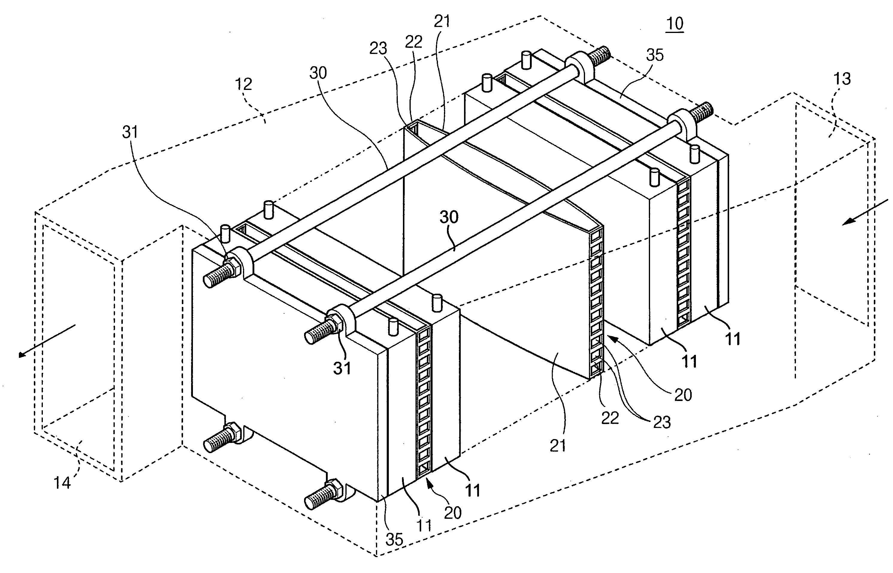
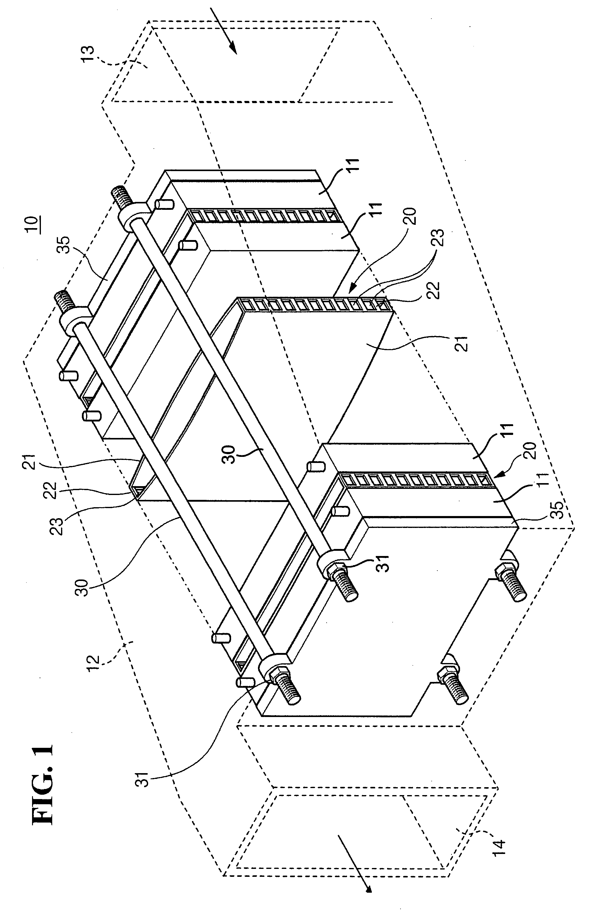
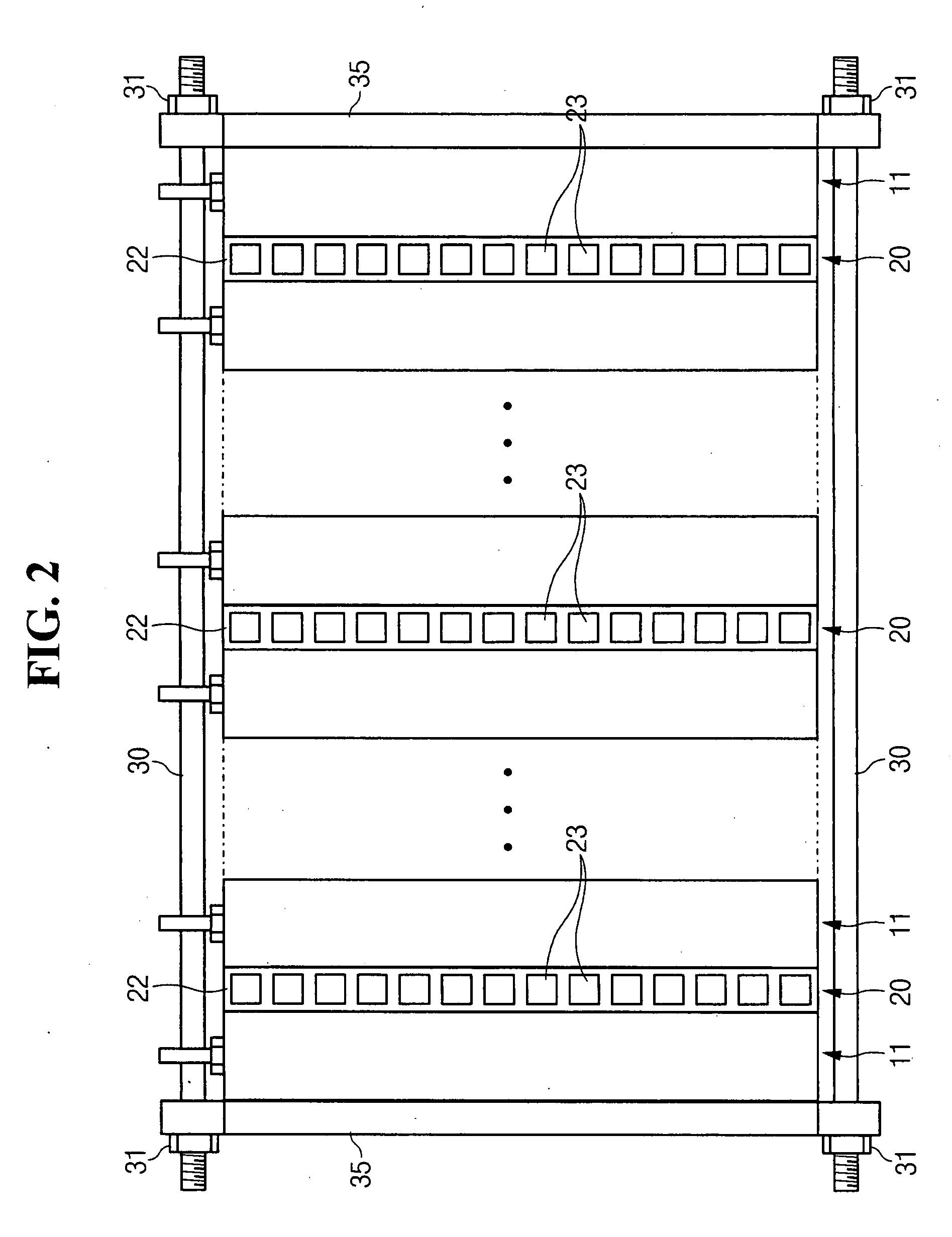
[0044]Referring to FIG. 1, battery module 10 is a high capacity battery module and includes a plurality of unit batteries 11 whic...


PUM


Abstract

A battery module includes a plurality of unit batteries and barriers which are interposed between the unit batteries. The barriers have front surfaces which contact the unit batteries and which are curved to bend elastically. The barriers have side surfaces which interconnect the front surfaces, and which have pathways through which a heat transfer medium flows. Connecting rods and nuts interconnect end plates of the battery module so as to press the unit batteries and the barriers together.

Description

CLAIM OF PRIORITY[0001]This application makes reference to, incorporates the same herein, and claims all benefits accruing under 35 U.S.C. §119 from an application for SECONDARY BATTERY MODULE earlier filed in the Korean Intellectual Property Office on the 9th of Jun. 2006 and there duly assigned Serial No. 10-2006-0051953.BACKGROUND OF THE INVENTION[0002]1. Field of the Invention[0003]The present invention relates to a battery module which is constituted by stacking a plurality of unit batteries, and more particularly, to a battery module in which the structure of a barrier interposed between unit batteries is improved.[0004]2. Description of the Related Art[0005]Generally, a rechargeable battery can be discharged and then charged, unlike a primary battery which is not intended to be charged.[0006]A low capacity battery constructed with a packed battery cell is used for a portable small-sized electronic device such as a mobile phone, a laptop computer, and a camcorder. A high capac...

Claims


Application Information

Patent Timeline
IPC IPC(8): H02J7/00
CPCH01M2/0217H01M10/0413H01M10/0468H01M10/5004F28F2255/02H01M10/5038H01M10/5059F28F2275/10F28F2009/029H01M10/5032H01M10/647H01M10/652H01M10/6557H01M10/613Y02E60/10H01M50/103H01M50/20H01M50/10
Inventor JEON, YOON-CHEOLKIM, TAE-YONG
Owner SAMSUNG SDI CO LTD
Learn More