
Dilating Trocar

a trocar and axial force technology, applied in the field of trocars, can solve the problems of inconvenient operation, inability to adjust the axial force, and the probability of injury to the internal organs of patients, and achieve the effects of improving the convenience of operation, reducing the axial force of surgeons, and being reliable and relatively inexpensiv

Inactive Publication Date: 2007-12-06
POPOV
View PDF4 Cites 7 Cited by
  • Summary
  • Abstract
  • Description
  • Claims
  • Application Information

AI Technical Summary

Benefits of technology

[0005] Another attempt is disclosed in U.S. Pat. No. 6,309,349 “Surgical retractor and stabilizing device” for the performance of closed-chest exploratory or surgical procedures on a patient. The surgical retractor is provided with two opposable blades to be inserted into previously made a surgical incision and forced apart by two control levers to form an access opening through which an instrument may be inserted into the thoracic cavity. In this invention, the axial force needed for the retractor emplacement is reduced to a minimum. The disadvantage of the invention is the increased injury of patient's body by the relatively large previous incision needed for inserting the blade edges and for forming the ovoid access opening. The latter is needed for preventing the body's tissue from substantial protrusion into the surgical instrument operation zone of the access opening on the open sides of the access opening. Carrying out the large through previous incision also is inconvenient and takes curtain time. Another disadvantage is the restricted application field of the invention, suitable for the thoracic surgery and non-applicable in the abdominal surgery.
[0006] The objective of the present invention is substantial decrease of surgeon's axial force needed for the trocar emplacement.
[0007] Another objective is substantial decrease the patient's tissue injury.
[0009] Another objective is enhancing the safety of the trocar operation.
[0010] Another objective is reducing the time needed for the trocar emplacement.
[0011] Another objective is providing the reliable and relatively inexpensive design of the trocar.

Problems solved by technology

This leads to the operation inconvenience and creates the probability of the injury of patients internal organs by sharp trocar tip at the early moment of the trocar introduction into a patient's cavity.
However, this solution is undesirable because of the increased injury of the patients tissue.
The disadvantage of this method is considerable spending the operation time caused with many operations needed for the cannula emplacement.
Another disadvantage is the large axial force needed for inserting the dilator and cannula into initially small-sized sleeve.
This force inevitably leads to great pressing onto patient's internal organs, which can be transformed into strokes due to uneven advance of the cannula within the sleeve.
Moreover, the necessary great axial force causes the inconvenience in a surgeon operation.
Another disadvantage is the increased injury of the abdominal wall due to excessive stretch of the body tissue, leading to a tissue ruptures and forming an avulsive wound.
The disadvantage of the invention is the increased injury of patient's body by the relatively large previous incision needed for inserting the blade edges and for forming the ovoid access opening.
Carrying out the large through previous incision also is inconvenient and takes curtain time.
Another disadvantage is the restricted application field of the invention, suitable for the thoracic surgery and non-applicable in the abdominal surgery.

Method used


Image

  • Dilating Trocar
  • Dilating Trocar
  • Dilating Trocar

Examples


Embodiment Construction

[0038] The detailed description of the present invention is offered with references made to the enclosed drawings in FIGS. 1 to 30.

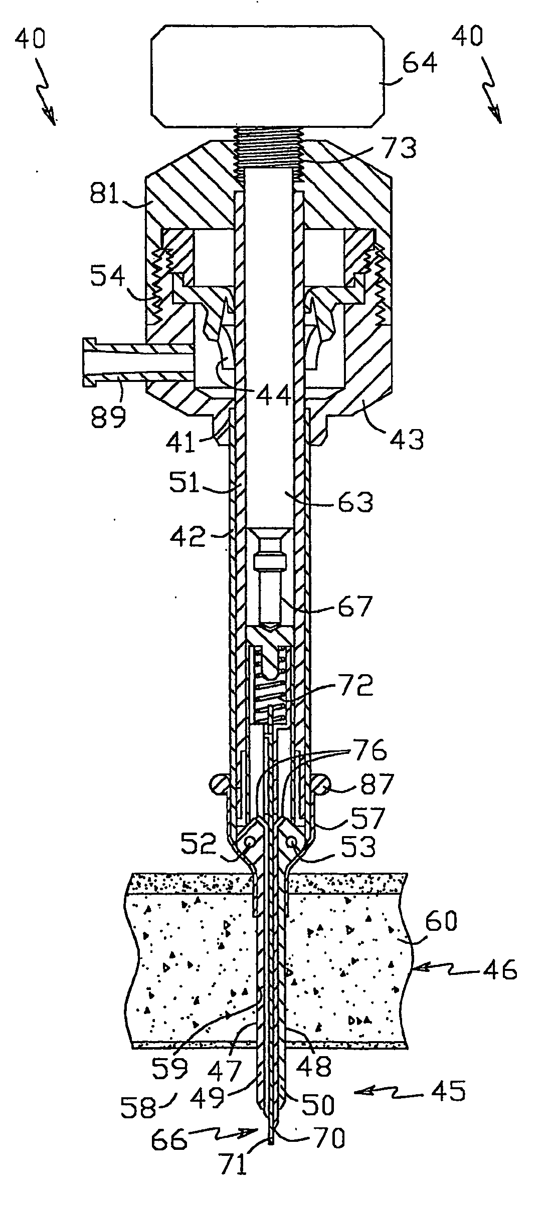
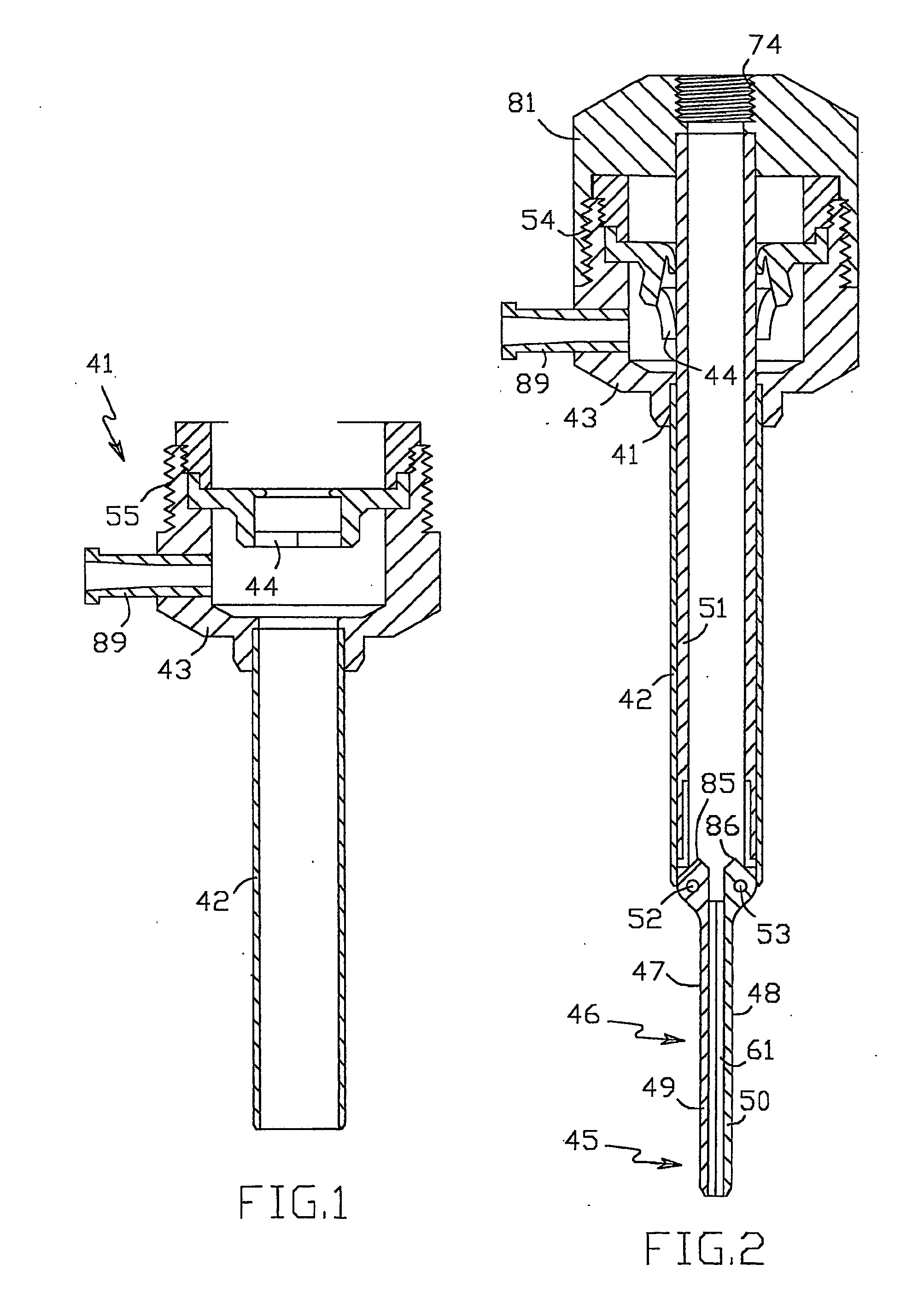
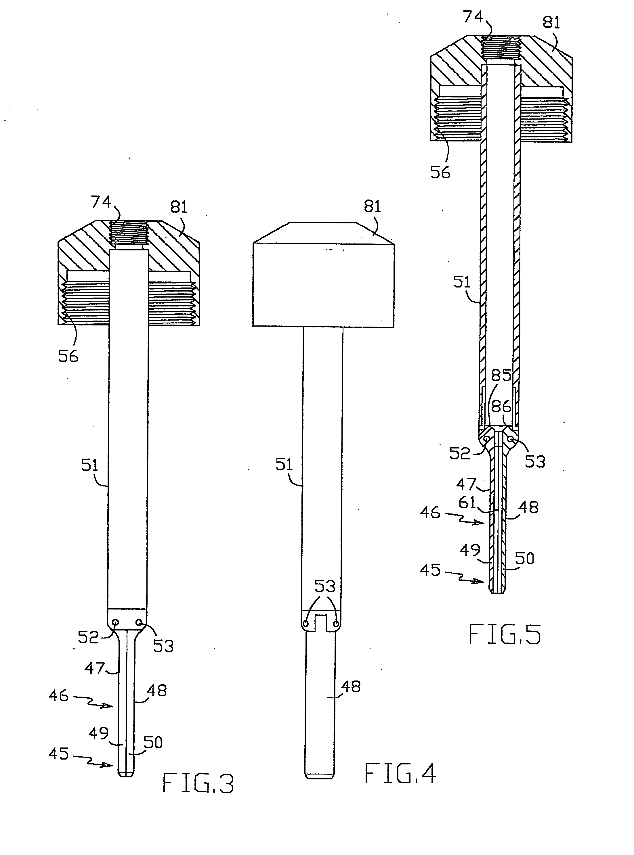
[0039] The dilating trocar 40, shown in FIGS. 1 to 17, comprises cannula 41 having tubular passageway portion 42 and housing 43 with sealing valve 44 disposed at the proximal end of passageway portion 42 and a dilating means including distal portion 45 and dilating portion 46 of changeable geometry having dilating surfaces 47, 48 and disposed adjacent to distal portion 45 proximally of it. Distal and dilating portions 45, 46 are made in the form of two dilating members 49 and 50 pivotably connected to carrier 51 by hinges 52 and 53. Carrier 51 (FIGS. 3 to 5) is designed for removable insertion inside passageway portion 42 and releasable engagement with cannula housing 43 by thread connection 54 (FIG. 2) including thread 55 on cannula housing 43 and thread 56 on carrier 51. There is sealing element 57 (FIG. 10) in the form of a resilient sleeve with flan...


PUM


Abstract

Dilating trocar (40) (see FIG. 14) comprises cannula (42) containing carrier (51) with pivotable dilating members (49, 50) of small transversal dimensions protruding distally of the cannula. Obturator (63) is housed inside the carrier and has sharp element (70) with underspringed protective shield (71) protrudind distally of the dilating members. After inserting the closed dilating members into a small opening primary made in patient's body cavity wall (60) by sharp element (70), user removes the obturator, introduces an actuating rod into carrier (51) and forces apart the dilating members rotating them about axes (52, 53) and thereby stretching the primary opening to provide the cannula insertion therein. Finally, user removes the actuating rod, carrier and dilating members from cannula (42) remaining the cannula in patient's body.

Description

BACKGROUND [0001] 1. Field of the Invention [0002] The present invention relates to surgical instruments designed for providing the access to patient's body cavity in the minimal invasive surgery (MIS). Specifically, it relates to the trocar devices designed for forming an opening in the body cavity wall and installing an access port therein for the performance of surgery operations. [0003] 2. Prior Art of the Invention [0004] The general feature of the many modern trocars is the use of considerable operators axial force needed for the trocar advance into the patients body tissue. This leads to the operation inconvenience and creates the probability of the injury of patients internal organs by sharp trocar tip at the early moment of the trocar introduction into a patient's cavity. The increased tissue incision allows partial solving this problem. However, this solution is undesirable because of the increased injury of the patients tissue. The attempt of the solution of the indicated...

Claims


Application Information

Patent Timeline
Patent Type & Authority Applications(United States)
IPC IPC(8): A61M29/02A61BA61B17/34A61M5/178
CPCA61B17/3417A61B2017/3484A61B17/3439
Inventor POPOV
Owner POPOV
Learn More