
Steerable medical instrument

Inactive Publication Date: 2007-12-06
COMMAND ENDOSCOPIC TECH
View PDF42 Cites 145 Cited by
  • Summary
  • Abstract
  • Description
  • Claims
  • Application Information

AI Technical Summary

Benefits of technology

[0008] One aspect of the present invention is a steerable medical instrument comprising (i) a shaft comprising a proximal end and a distal end; (ii) an end effector at the distal end of the shaft, said end effector comprising a proximal end and a distal end; (iii) one or more steering control wires anchored in the end effector such that tension applied to the wire proximal t

Problems solved by technology

Navigating channels in the human body can be very challenging.
Some parts of the human anatomy can be difficult to see and are not always oriented in a convenient location relative to the position of the scope or surgical instrument.
Occasionally, the anatomy and the degrees of freedom of the instruments can impede or prevent successful navigation.
Still, many procedures using steerable instruments remain difficult.

Method used


Image

  • Steerable medical instrument
  • Steerable medical instrument
  • Steerable medical instrument

Examples


Embodiment Construction

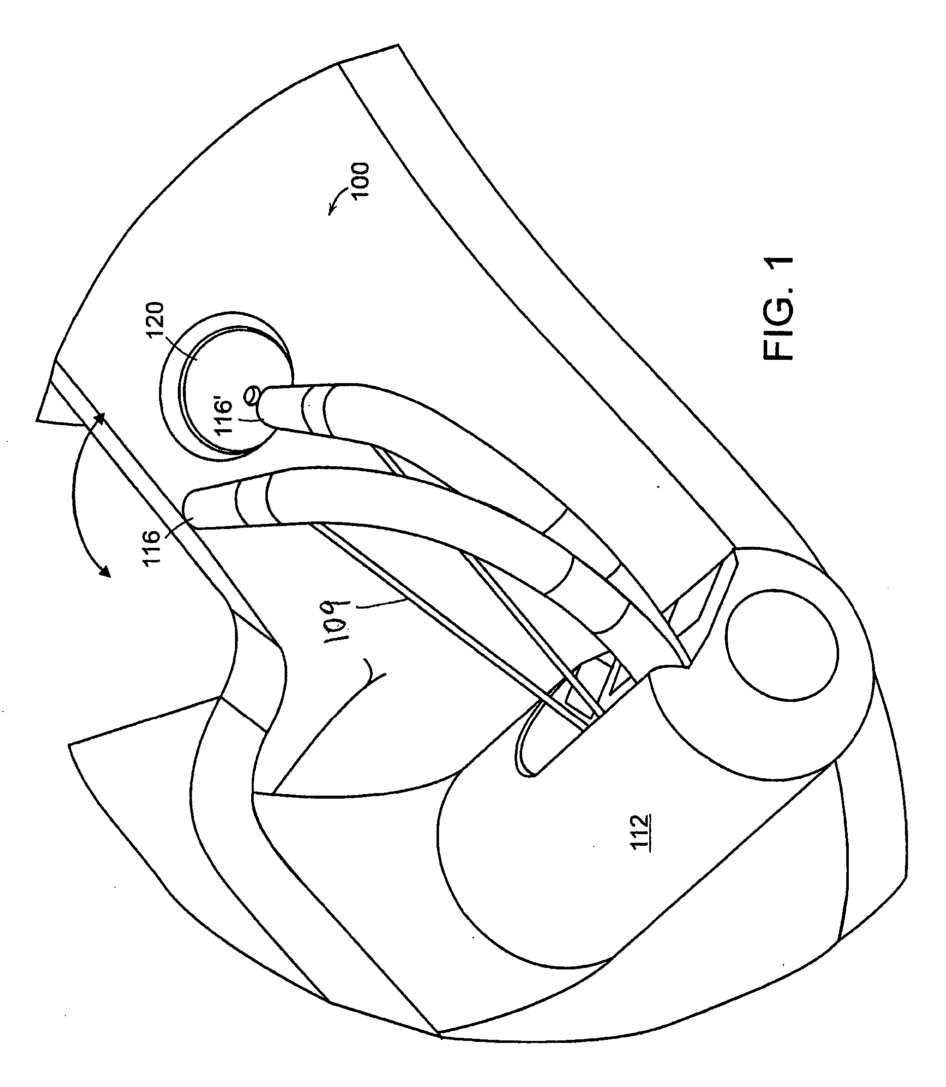
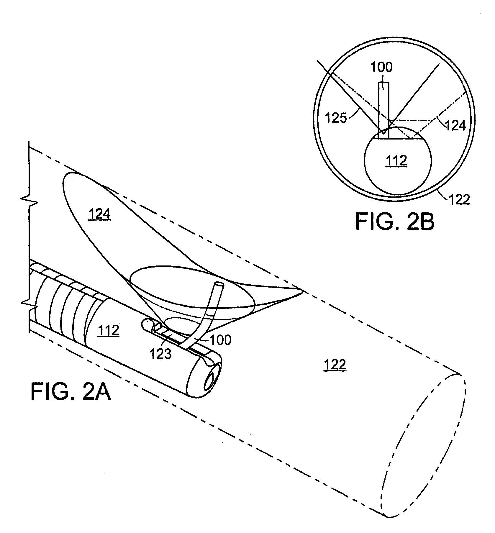
[0067]FIG. 1 shows the positioning of an end effector 100 of a steerable medical instrument, according to the invention. In this embodiment, the instrument is a sphincterome with a cutting wire 109 in the bowed position, emerging from the distal end of an endoscope 112. The end effector 100 can be moved from a first position 116 to a second position 116′ to orient the end effector 100 to a particular location in the body, such as a papilla 120. In the first position 116, the end effector is in the same plane as the scope. In the second position 116′, the end effector is adjusted out of the plane of the scope in any direction, and in this fashion may be aligned with the axis of the papilla 120. Multi-directional control of the end effector permits the user to control the angle of exit of the end effector from the scope; position the distal tip of an end effector in relation to the patient's anatomy; position a cutting wire (in the case of a sphincterotome) in the correct plane to ena...


PUM


Abstract

A steerable medical instrument includes a control handle, a shaft, steering control wires, and an end effector at the distal end of the shaft. The end effector is a separate component engineered to distribute the stress and strain of bending moments along the length of the end effector to achieve predicable, repeatable, fine motion control over the distal end of the instrument. The end effector may be customized for any medical application. For example, the end effector may comprise a grasping device, a cutting devise, a snare, a specimen retrieval device, or a wound closure device (such as a stapler).

Description

CROSS-REFERENCE TO RELATED APPLICATION [0001] This application claims the benefit of and priority to U.S. provisional patent application No. 60 / 801,705 filed on May 19, 2006, which is owned by the assignee of the instant application and the disclosure of which is incorporated herein by reference in its entirety.FIELD OF THE INVENTION [0002] This invention relates to the field of multidirectional medical instruments, and more specifically, to steerable surgical instruments. BACKGROUND OF THE INVENTION [0003] A number of diagnostic and treatment procedures, once performed surgically through an open wound, are now performed in a less invasive manner with viewing scopes (such as endoscopes and laparoscopes) and catheter instruments. Examples of such instruments include, for example, ERCP cannulas, sphincterotomes (also known as papillotomes), stone balloon catheters and balloon dilatation catheters. [0004] Traditional procedures in which such instruments are utilized include, for exampl...

Claims


Application Information

Patent Timeline
IPC IPC(8): A61B17/22
CPCA61B17/00A61B1/0057A61B18/1492A61B2017/003A61B2017/00323A61B2017/00867A61B2018/00482A61B2018/00494A61B2018/00595A61B2018/1407A61B2018/144A61M25/0029A61M25/0136A61M25/0138A61M25/0147A61M2025/0036A61M2025/004A61M2025/0163A61B1/0052A61B1/0055A61B17/32056
Inventor REMISZEWSKI, STANABRAMS, MICHAEL E.MASTRI, DOMINICK L.GAMBALE, RICHRADZIUNAS, JEFFREYGREEN, RONALD L.FERREIRA, DANIAL
Owner COMMAND ENDOSCOPIC TECH
Learn More