Truss Cable Semi-submersible Floater for Offshore Wind Turbines and Construction Methods

a technology of truss cable and floater, which is applied in the direction of special-purpose vessels, vessel construction, transportation and packaging, etc., can solve the problems of large oil and gas steel structure and hull form, and achieve the effects of improving stability, structural strength and dynamic performance, and reducing cost and weigh

Inactive Publication Date: 2012-05-03
WANG JIN +1
View PDF8 Cites 60 Cited by
  • Summary
  • Abstract
  • Description
  • Claims
  • Application Information

AI Technical Summary

Benefits of technology

[0009]Truss cable semi-submersible floater for offshore wind turbines and construction methods are provided to provide more cost and weight efficient floater

Problems solved by technology

This kind of oil and gas steel structu

Method used


Image

  • Truss Cable Semi-submersible Floater for Offshore Wind Turbines and Construction Methods
  • Truss Cable Semi-submersible Floater for Offshore Wind Turbines and Construction Methods
  • Truss Cable Semi-submersible Floater for Offshore Wind Turbines and Construction Methods

Examples


Embodiment Construction

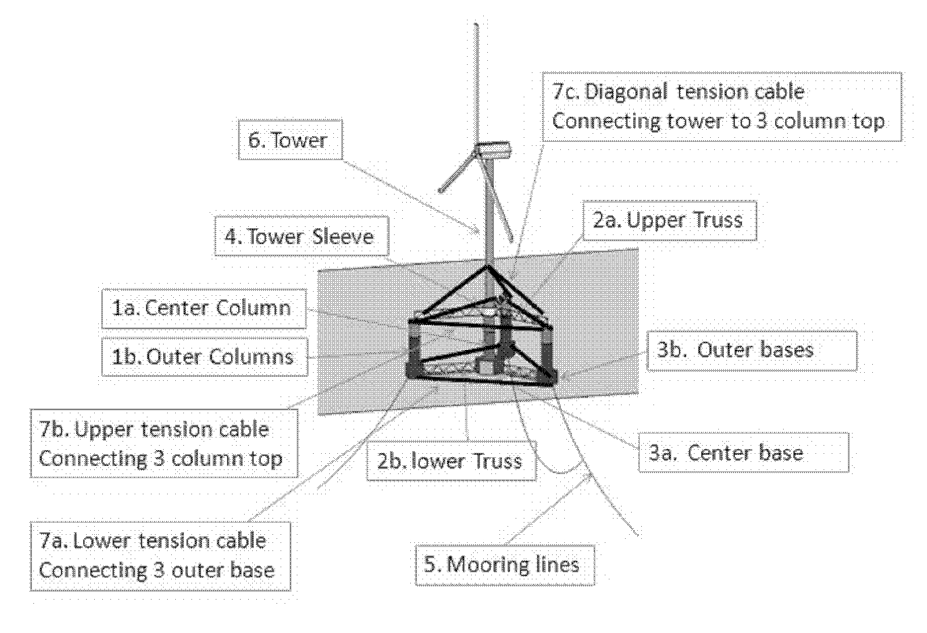
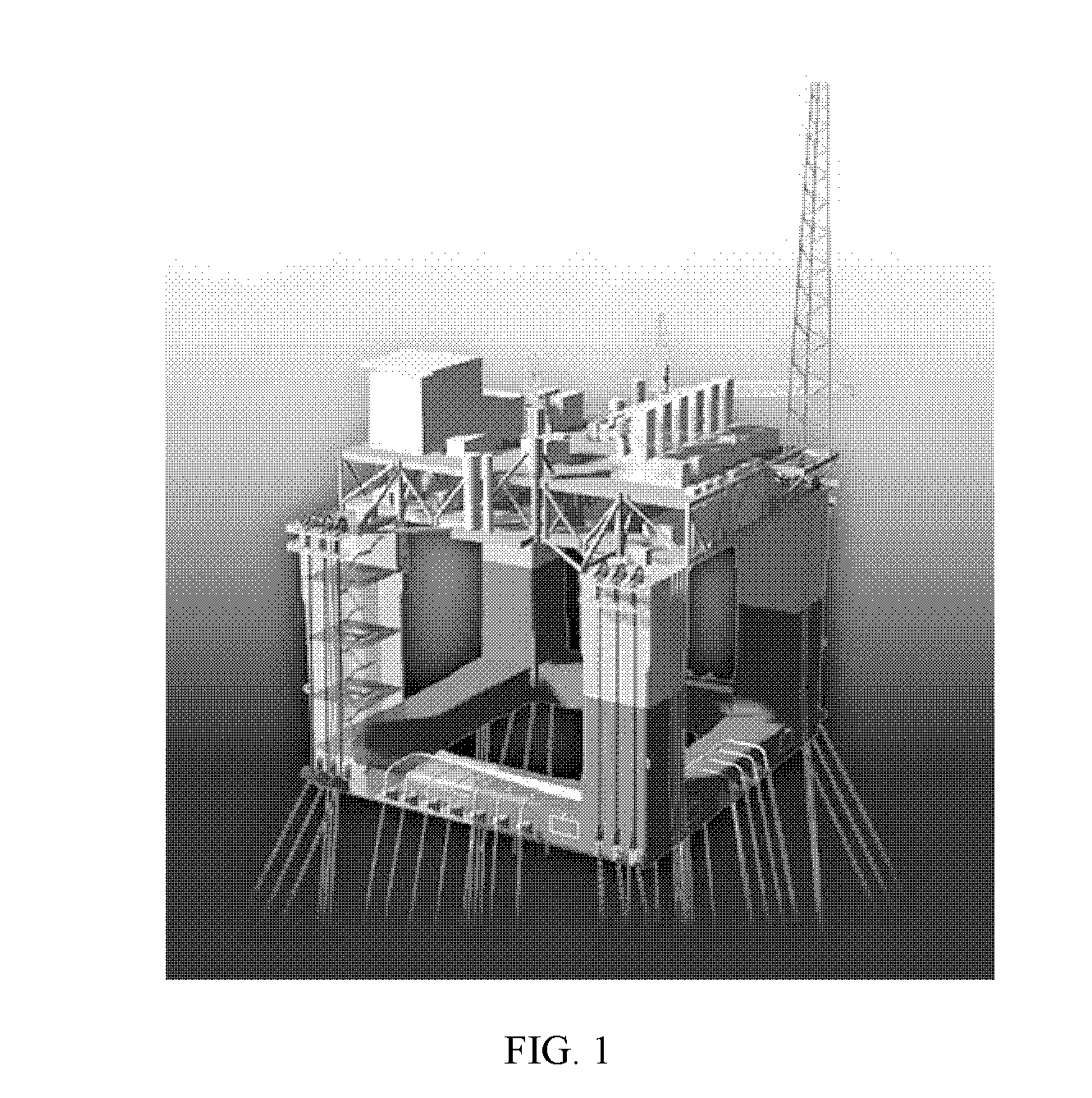
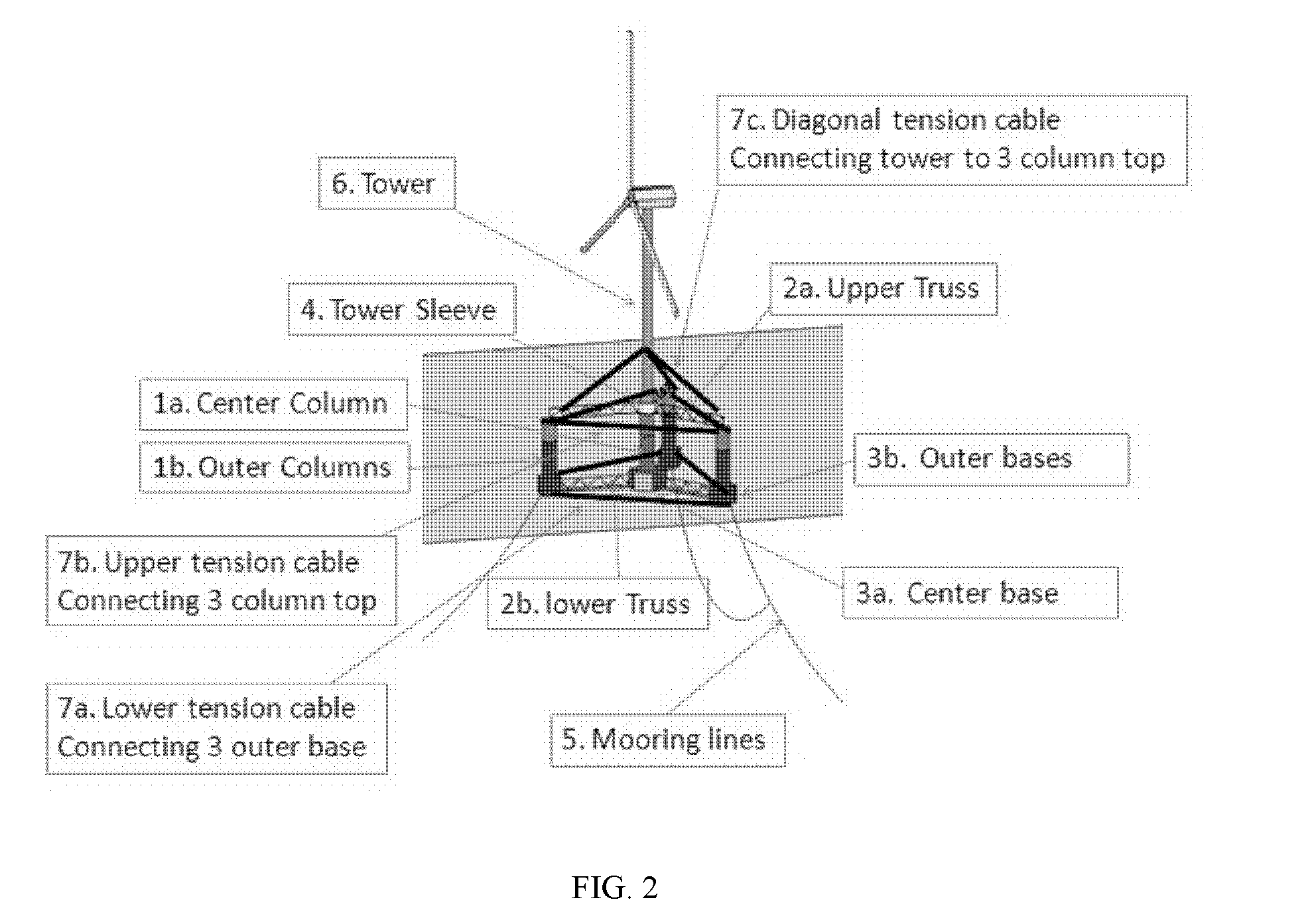
[0016]With reference to FIG. 2, a truss cable semi-submersible floater (hereinafter referred as “floater”) includes a hull, a tower, and a tensioned cable system. The hull mainly includes 3 components: columns, including a center column 1a and outer columns 1b, trusses coupled to the columns, including an upper truss 2a and a lower truss 2b, and column bases coupled to the columns and the trusses, including a center base 3a and outer bases 3b. The hull can have multiple outer columns for stability, typically 3 columns (as shown in FIG. 2), but also can have 4 columns or more. The hull has an in-service draft in the order of 60 ft to 80 ft depending on metocean conditions of the deployed area. The columns are most buoyant to provide the buoyancy for the wind turbine and rotor blades, which can be coupled with the floater and located above the water surface. The column bases, which can be tanks, provide stability for wet tow and hold ballast (sold or water ballast) for inplace conditi...


PUM


Abstract

Truss cable semi-submersible floater for offshore wind turbines and construction methods are provided. A floating system includes a hull, a tensioned cable system, and a tower. The hull includes vertical buoyant columns with one column at the center of the pattern, larger size column base tanks, and a truss system, all of which are coupled to each other for supporting the tower and wind turbines. The column can be made of hybrid materials, including steel and composite-concrete. The steel section and the composite-concrete section of the column can be connected by grouting. The tensioned cable system including upper, lower, and diagonal tensioned cables to connect the column, the column base, and the tower to reduce the bending moments and improve stability, strength and dynamic performance of the hull structure.

Description

CROSS-REFERENCE TO RELATED APPLICATIONS[0001]This present application claims the benefits of priority from the United States of America provisional application No. 61 / 407,730, entitled “TRUSS CABLE SEMI-SUBMERSIBLE FLOATER FOR OFFSHORE WIND TURBINES AND CONSTRUCTION METHODS”, filed on Oct. 28, 2010.STATEMENT REGARDING FEDERALLY SPONSORED RESEARCH OR DEVELOPMENT[0002]Not applicable.REFERENCES[0003](1) U.S. Pat. No. : 4,702,321, Filing date: Sep. 20, 1985, Issue date: Oct. 27, 1987[0004](2) U.S. Pat. No. : 6,263,824, Filing date: Dec. 23, 1997, Issue date: Jul. 24, 2001[0005](3) U.S. Pat. No. : 7,819,073, Filing date: Jun. 2, 2006, Issue date: Oct. 26, 2010[0006](4) U.S. Pat. No. : 7,612,462, Filing date: Apr. 24, 2008, Issue date: Nov. 3, 2009FIELD OF INVENTION[0007]Embodiments of present invention relate generally to the field of floating offshore wind turbines for offshore wind power generation. More particularly, embodiments of present invention relate to the field of a semi-subme...

Claims


Application Information

Patent Timeline
IPC IPC(8): B63B35/44B63B21/50
CPCB63B21/50Y02E10/727B63B35/44
Inventor GONG, LINGWANG, JIN
Owner WANG JIN
Why Eureka
Try Eureka