System and Method for Asymmetrically Adjusting Compensation Applied to a Signal

a compensation and signal technology, applied in the field of signal communication, can solve problems such as attenuation of signals from phenomena, and achieve the effects of avoiding delay in convergence time, potential instability, and improving component sensitivity

Inactive Publication Date: 2007-12-06
FUJITSU LTD
View PDF80 Cites 35 Cited by
  • Summary
  • Abstract
  • Description
  • Claims
  • Application Information

AI Technical Summary

Benefits of technology

[0005]One technical advantage of certain embodiments is equalizing output signals. Certain embodiments compensate for signal attenuation resulting from the communication media used to communicate the signal. This allows the output characteristics of the signal to remain consistent independently of the communication path used to communicate the signal. Advantages associated with consistent output characteristics may include improved component response, as the signal level can be selected to fall within the dynamic range of system components. Furthermore, the signal can be maintained at a sufficient level to prevent information from being lost.
[0018]Another technical advantage of particular embodiments is dynamically generating a control target for an average value of a binary objective variable (e.g., ISI level, equalization level, or other suitable objective variable) in an equilibrium state. In particular embodiments, the optimal average ISI level is likely to be high for a high loss channel and low for a low loss channel. Thus, embodiments comprising a control target for the average value of a binary objective variable that dynamically varies with the value of the control variable may be advantageous.

Problems solved by technology

When signals are communicated over communication media, the signals may suffer attenuation from phenomena such as skin effect and dielectric absorption.

Method used


Image

  • System and Method for Asymmetrically Adjusting Compensation Applied to a Signal
  • System and Method for Asymmetrically Adjusting Compensation Applied to a Signal
  • System and Method for Asymmetrically Adjusting Compensation Applied to a Signal

Examples


Embodiment Construction

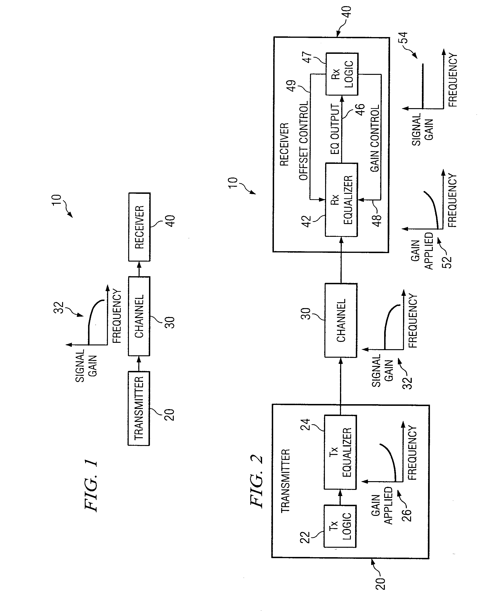
[0072]FIG. 1 is a block diagram illustrating an example digital signal transmission system 10. Digital signal transmission system 10 comprises transmitter 20, communication channel 30, and receiver 40. Transmitter 20 may comprise any suitable transmitter operable to transmit signals carrying digital information to receiver 40 over channel 30. In particular embodiments, transmitter 20 may communicate information at relatively fast rates. Channel 30 may comprise any suitable channel or other communication medium. Channel 30 may include, for example, a cable carrying a signal, an insulator insulating the cable, packaging around the cable, and / or connectors. Channel 30 is operable to receive signals from transmitter 20 and forward these signals to receiver 40. Receiver 40 may comprise any suitable receiver operable to receive signals from transmitter 20 over channel 30 and process the digital information in the received signals suitably.

[0073]In typical digital signal transmission syste...


PUM


Abstract

In one embodiment of the present invention, a method for adjusting a signal includes applying at least one of a loss compensation for frequency-dependent distortion and an offset compensation for DC-offset distortion to a signal before or after the distortion occurs to generate an output signal. The method also includes, using a clock signal, sampling the output signal to generate a plurality of data values and boundary values, each value comprising either a high value or a low value based on the sampling of the output signal. The method further includes, based only on the high or low value of one or more of the data values and boundary values, adjusting at least one of the loss compensation and the offset compensation applied to the signal, where if the at least one of the loss compensation and the offset compensation applied to the signal is to be increased, the at least one of the loss compensation and the offset compensation is increased by a first amount, if the at least one of the loss compensation and the offset compensation applied to the signal is to be decreased, the at least one of the loss compensation and the offset compensation is decreased by a second amount, and the magnitude of the first amount is not equal to the magnitude of the second amount.

Description

CROSS-REFERENCE TO RELATED APPLICATION[0001]This application claims the benefit of priority under 35 U.S.C. § 119(e) of U.S. Provisional Application entitled “Adaptive Equalizer,” Ser. No. 60 / 803,451 filed May 30, 2006.TECHNICAL FIELD OF THE INVENTION[0002]This invention relates generally to signal communication and, more particularly, to a system and method for asymmetrically adjusting compensation applied to a signal.BACKGROUND OF THE INVENTION[0003]When signals are communicated over communication media, the signals may suffer attenuation from phenomena such as skin effect and dielectric absorption. Signal receivers may include equalizers that compensate for this attenuation in order to improve the accuracy and efficiency of signal communication. It is desirable for the amount of compensation applied by equalizers to match the level of attenuation due to the media as closely as possible, in order to keep the output characteristics of the signal consistent independently of the part...

Claims


Application Information

Patent Timeline
Patent Type & Authority Applications(United States)
IPC IPC(8): H04B1/10
CPCG01D21/00H04L25/03038H04L25/03114H04L2025/03681H04L25/061H04L2025/03611H04L25/03343
Inventor HIDAKA, YASUO
Owner FUJITSU LTD
Why Eureka
Try Eureka