
Data Unit Sender Control Method

a data unit and sender technology, applied in data switching networks, high-level techniques, frequency-division multiplexes, etc., can solve the problems of limit on how much data can be sent per rtt, limit rate, etc., to improve flow control, improve congestion window, and adapt to the situation better

Inactive Publication Date: 2007-12-06
TELEFON AB LM ERICSSON (PUBL)
View PDF9 Cites 22 Cited by
  • Summary
  • Abstract
  • Description
  • Claims
  • Application Information

AI Technical Summary

Benefits of technology

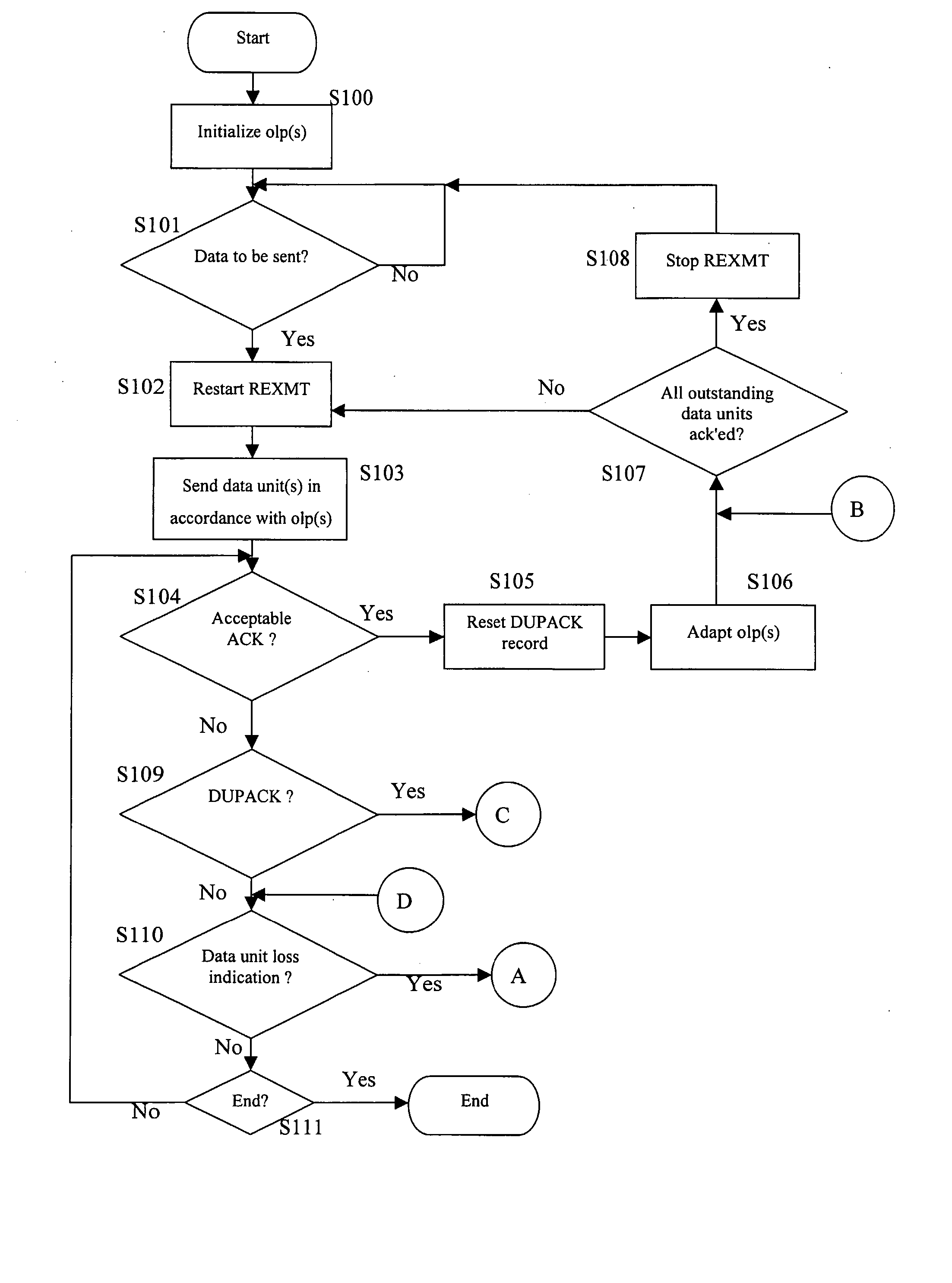
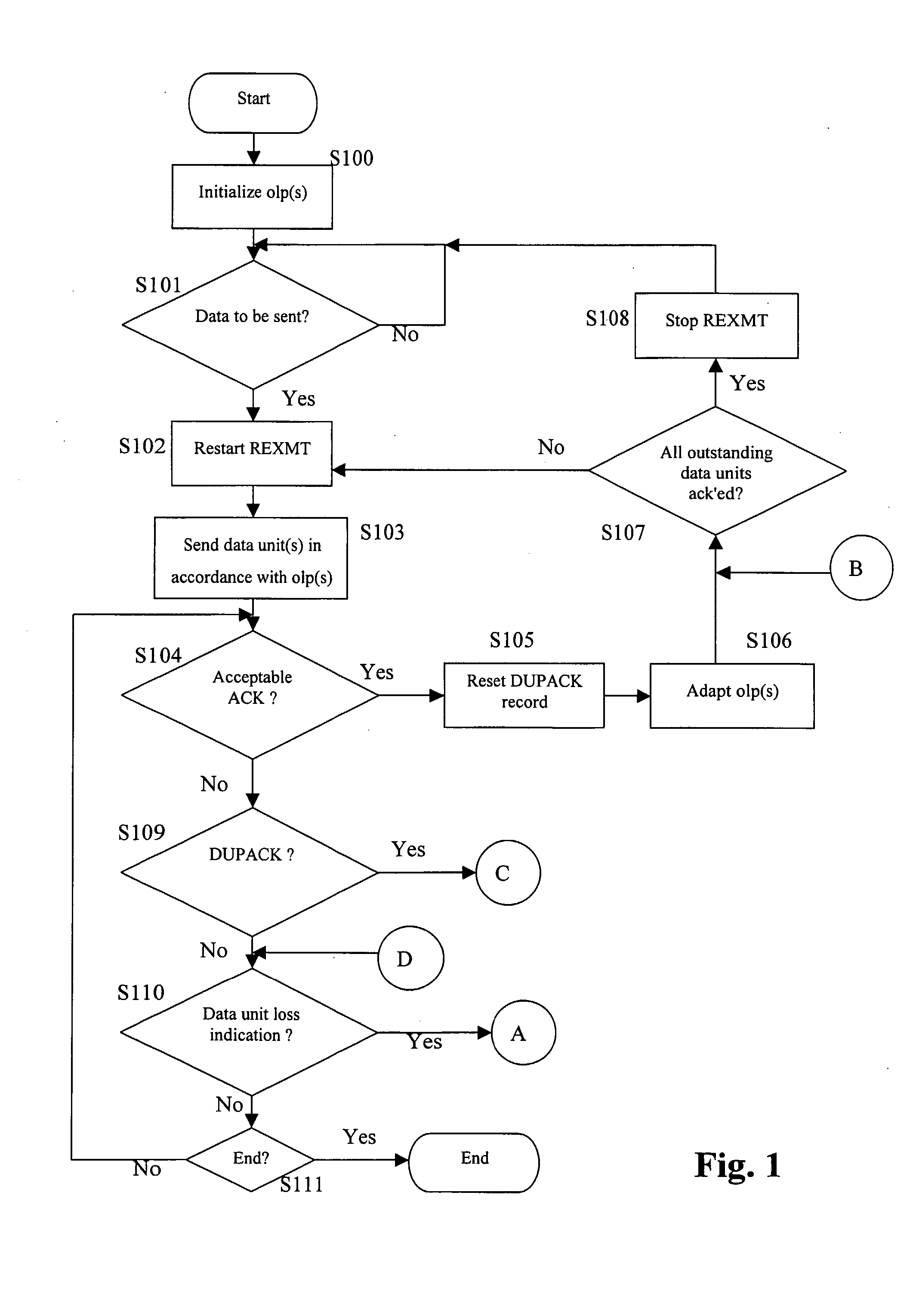
[0034] An important advantage of the concept of the present invention is that the performance of the first data unit sender becomes independent of events such as sudden delay spikes or packet reordering. Namely, a data unit loss indication (such as a time-out or a predetermined number of duplicate acknowledgments) caused by reordering or a delay spike can be identified as not being due to an actual loss, and the conventional congestion response step, which reduces the sender's output by reducing the send rate, can be avoided. As a consequence, reordering and delay spikes do not lead to an unnecessary reduction in sending performance. This in turn means that the conventional requirement of in-order-delivery from the second layer upward on the receiving side can be dropped. Therefore, the implementation of the second layer components can be greatly simplified. The requirement of in-order-delivery requires considerable resources, such as re-sequencing buffers. In the present invention, these re-sequencing buffers are not necessary. Also, the entire second layer design is simpler.
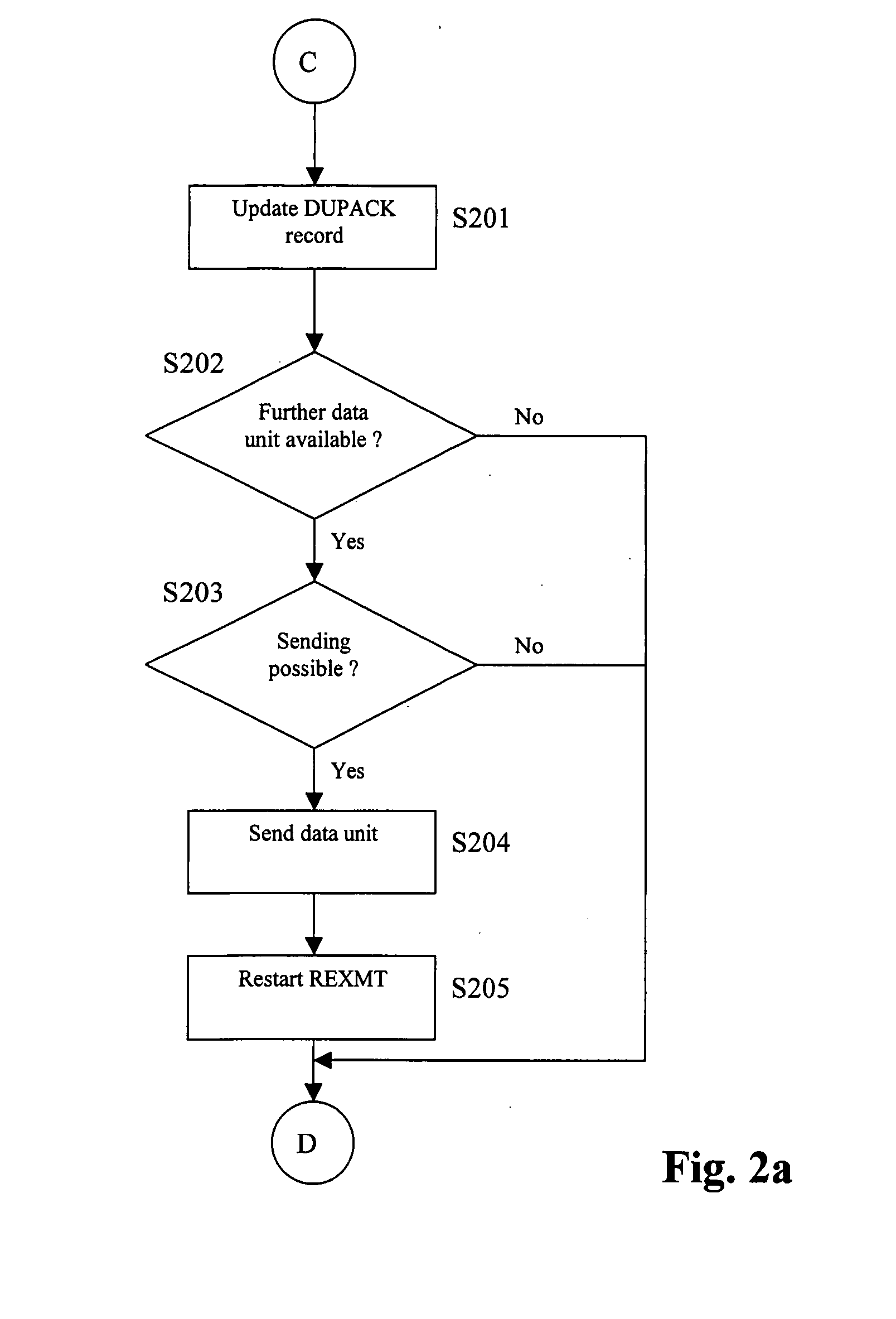
[0041] Duplicate acknowledgment messages indicate the correct receipt of data units, albeit out of order. If it is later determined that the data unit loss indication does not relate to an actual data unit loss, then one may conclude that reordering has occurred. This means that if the reordering had not occurred, then the duplicate acknowledgments would have been acceptable acknowledgments, which in turn would have been used by the sender to adapt the output limiting parameter, e.g. increase the congestion window in a window-based scheme. The present aspect of the invention therefore teaches to use information on the duplicate acknowledgments with respect to adapting the output limiting parameter(s) if it is distinguished that no data unit loss has occurred. The output limiting parameter is thereby better adapted to the situation, which leads to better and more efficient flow control.

Problems solved by technology

Therefore, the congestion window also limits the amount of data that the sending peer can send at one time.
Due to the fact that a certain amount of time passes between sending a data unit and receiving an associated acknowledgment, the so-called round-trip-time (RTT), the result of the congestion window is a limit on how much data can be sent per RTT, which amounts to a rate limitation.
For example, the expiring of a re-transmission timer or the repeated sending of feedback messages that indicate a missing data unit can also be caused by the delaying of a data unit in the network.
Such delaying can lead to the phenomenon of re-ordering, in which a later sent data unit arrives at the receiver before an earlier sent one, such that the receiver detects the earlier sent data unit as missing.
Such delaying can also lead to so-called delay spikes, in which an entire group of data units is delayed, however, without any reordering taking place.

Method used


Image

  • Data Unit Sender Control Method
  • Data Unit Sender Control Method
  • Data Unit Sender Control Method

Examples


Embodiment Construction

[0050] In the following, the description will make reference to specific protocol layers, such as the link layer and the network layer, and to specific protocols, such as TCP, but it should be noted that the present invention is by no means restricted to such specific layers or specific protocols, as it can be applied in the context of any data unit sender that acts as a sending peer of a protocol that uses cumulative acknowledgments.

[0051] Nonetheless, the concept of the present invention can preferably be applied to TCP or a TCP-like protocol. A TCP-like protocol is a communication protocol that is like TCP at least in the following characteristics: the flow control is window-based, the sender is arranged to send data units in a sequence, each data unit carrying a sequence position identifier, and the data unit receiver is arranged to acknowledge the correct receipt of data units with acknowledgment messages that carry the sequence position identifier indicative of the last data ...


PUM


Abstract

A method of controlling a data unit sender is described. A flow control procedure for controlling the flow of data units sent by said data unit sender is conducted in dependence on acknowledgement messages from the receiver The flow control procedure utilizes (S103) at least one output limiting parameter (olp; cwnd) for placing a limit on the data units sender's current data send rate. A procedure is provided for detecting (S110) a data unit loss indication, in response to the detection of a data unit loss indication, performing (S311) a retransmission, subsequent to said retransmission (S311) waiting (S312) for an acceptable acknowledgment message carrying the sequence position identifier indicative of said data unit indicated as potentially having been lost, and distinguishing (S317) whether said acceptable acknowledgment message relates to an original transmission, and in response to distinguishing that said acceptable acknowledgment message does not relate to said original transmission, performing (S318) a congestion response step, while in response to distinguishing that said acceptable acknowledgment message relates to said original transmission, said output limiting parameter is adapted (S319) based on one or more duplicate acknowledgment messages received since receiving the last acceptable acknowledgment message that precedes the acceptable acknowledgment message carrying the sequence position identifier indicative of said data unit indicated as potentially having been lost.

Description

FIELD OF THE INVENTION [0001] The present invention relates to a method of controlling a data unit sender, to a corresponding data unit sender, to a communication system comprising first and second data unit senders and a data unit receiver, and to a method of controlling such a system. BACKGROUND OF THE INVENTION [0002] Data unit oriented communication is well-known. In data unit oriented communication, an amount of data is divided into one or more data units, where the structure of the data units is defined by a communication protocol to which the sender and receiver in the communication adhere. The protocol also defines how specific information is to be coded, and how the sender and / or receiver may react to specific information. Data unit oriented communication is also known as packet exchange communication. It should be noted that such units or sub-divisions of data are referred to by different names in connection with specific protocols, such as packets, frames, segments, proto...

Claims


Application Information

Patent Timeline
IPC IPC(8): H04L12/24H04L1/00H04L1/16H04L1/18
CPCH04L1/0002H04L1/0015H04L1/1635Y02B60/31H04L1/187H04L1/188H04L1/1678Y02D30/50
Inventor LUDWIG, REINERMEYER, MICHAELEKSTROM, HANNES
Owner TELEFON AB LM ERICSSON (PUBL)
Learn More