
Method For Supplying Energy And System Therefor

Inactive Publication Date: 2007-11-29
JFE R&D
View PDF5 Cites 9 Cited by
  • Summary
  • Abstract
  • Description
  • Claims
  • Application Information

AI Technical Summary

Benefits of technology

[0013] Fluctuations of electric power consumption in a grid, such as fluctuations in electric power consumption in a grid between day and night, are compensated for by an electric power storage device such as a secondary battery. However, since the electric power storage device is expensive, during a shortage of electric power, the supply of electric power inevitably depends on electric power supplied from another grid or an existing electric power plant. When an electric power shortage occurs in a grid, electric power is supplied from a power generator in another grid to the above grid, thereby compensating for the fluctuation of electric power consumption in the grid.
[0016] That is, the known method of supplying energy is an effective technique to some degree from the standpoint that surplus electric power is effectively utilized and the cost of electric power is reduced. However, this method is not a technique developed by combining fuel used for power generation and electric power.
[0017] Consequently, it is a second object of the present invention to provide a novel method of supplying energy in which fuel and electric power can be utilized while being associated with each other, and a system therefor.
[0033] According to the invention described in item (2), since dimethyl ether (DME), which is versatile, is used as fuel for a power generator and fuel for at least one of a combustion device and a transport device, the possibility of interchange of fuel can be increased between devices in a grid. Furthermore, energy can be supplied without developing a special supply infrastructure such as a pipeline, and thus an economical method of supplying energy can be provided. For example, existing electric power lines can be used for providing electric power, and it is sufficient that a storage tank is present in a grid for fuel supply. In particular, existing facilities for storing propane can be used as facilities for storing DME with a simple remodeling. Furthermore, each of the grids is not connected to a pipeline, and is an independent system. Consequently, damage can be reduced in the case of the occurrence of a disaster such as an earthquake, and the recovery is also easy when the system suffers from a disaster.
[0034] According to the invention described in item (3), the use of waste and the like can be expanded, and CO2 emission caused by combusting waste and the like can be reduced.
[0040] According to the invention described in item (9), since dimethyl ether (DME), which is versatile, is used as fuel for a power generator and fuel for at least one of a combustion device and a transport device, the possibility of interchange of fuel can be increased between devices in a grid.

Problems solved by technology

However, when this system is applied to consumers, supply and demand are not balanced.
This is caused by an imbalance described below, and even if sensible heat is recovered, it cannot be effectively used in some cases.
(1) Geographical imbalance: The site of supply and the site of demand are far from each other.
Therefore, an extremely large infrastructure is required in order to transport a large amount of energy, thus causing economical problems.
(2) Temporal imbalance: The temporal fluctuations of supply and demand cannot be matched.
For example, during daytime in summer, a large amount of electric power is consumed because of the use of air conditioners and the like, but the use of the sensible heat of hot water and the like is concentrated in the morning and evening and the demand thereof is also small in summer.
In order to correct this imbalance, a method of storing sensible heat has been studied, but the storage volume per quantity of sensible heat is larger than that of fuel or the like, thus causing economical problems.
(3) Qualitative imbalance: For example, sensible heat has low energy quality, and it is extremely difficult to use sensible heat as a motive energy source for transportation.

Method used


Image

  • Method For Supplying Energy And System Therefor
  • Method For Supplying Energy And System Therefor
  • Method For Supplying Energy And System Therefor

Examples


Embodiment Construction

[0053] In the present invention, DME is used as a novel medium for the energy cycle other than sensible heat. The reasons for the use of DME will now be sequentially described from the following viewpoints: 1. Medium that enables establishment of an energy cycle in society and 2. Energy supply system using DME.

1. Medium that Enables Establishment of an Energy Cycle in Society

[0054] In order to correct the imbalance between supply and demand, which is an obstacle in the formation of an energy cycle in society, a novel medium for the energy cycle other than sensible heat must be considered. It is believed that the following characteristics are required for the novel medium for the energy cycle.

(1) The medium has a high level of safety and the same economical efficiency as that of existing fuel.

[0055] Regarding safety, the substance itself serving as the medium must be nontoxic, and preferably, even after being combusted, does not result in the discharge of SOx, NOx, and particul...


PUM


Abstract

The sensible heat of an exhaust gas of a power generator, a combustion device, or a transport device 21 in a virtual area wherein a plurality of energy-consuming devices 23 are provided (energy supply and demand grid) is recovered as H2 or CO+H2 by reforming dimethyl ether (DME); and the H2 or CO+H2 is supplied as fuel for the energy-consuming devices 23 or as a chemical raw material within the energy supply and demand grid or to another energy supply and demand grid. By forming an energy cycle in society using DME, for example, waste heat of factories and electric power plants can be effectively utilized as energy in society as a whole, e.g., as energy for consumers or transportation.

Description

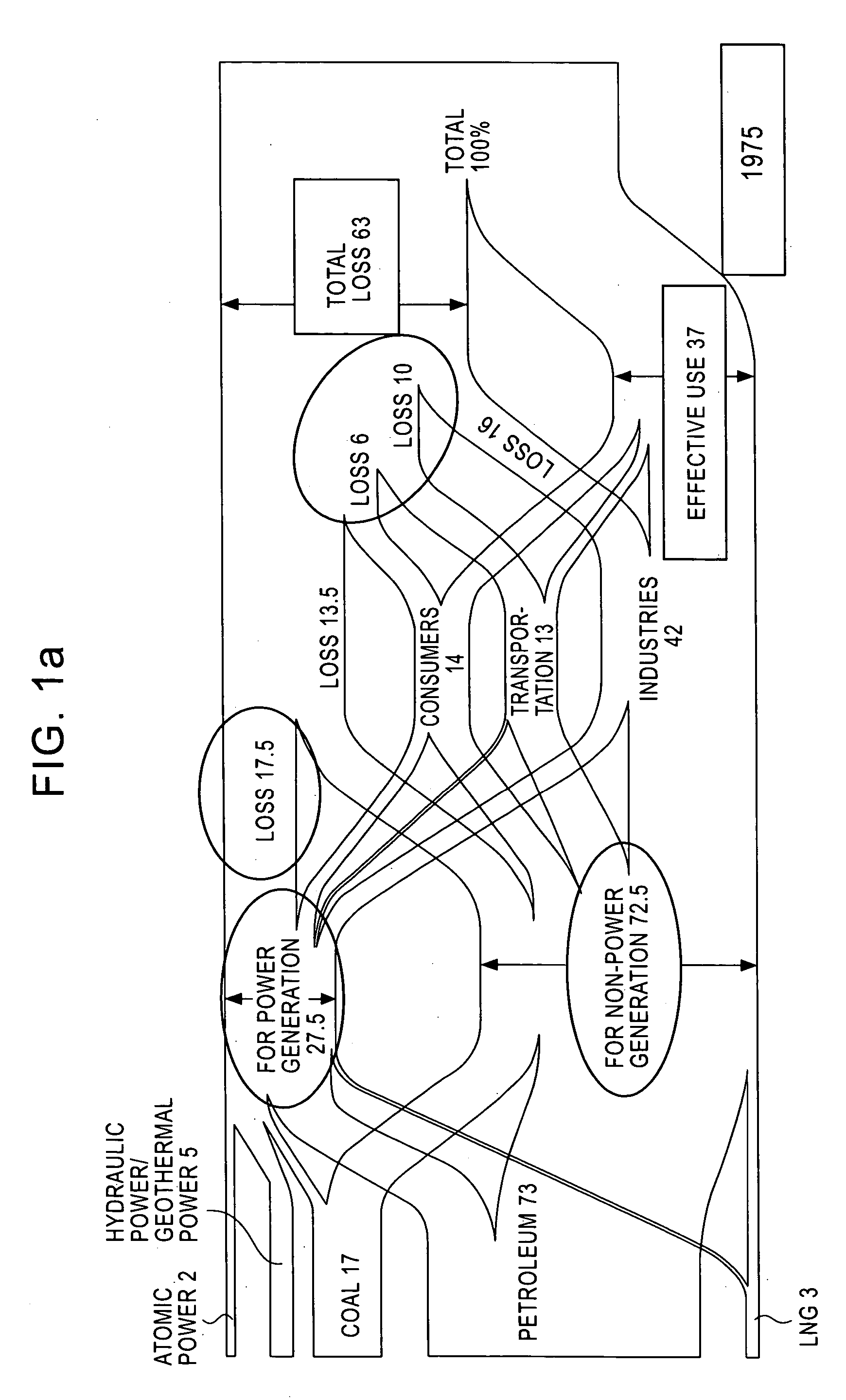
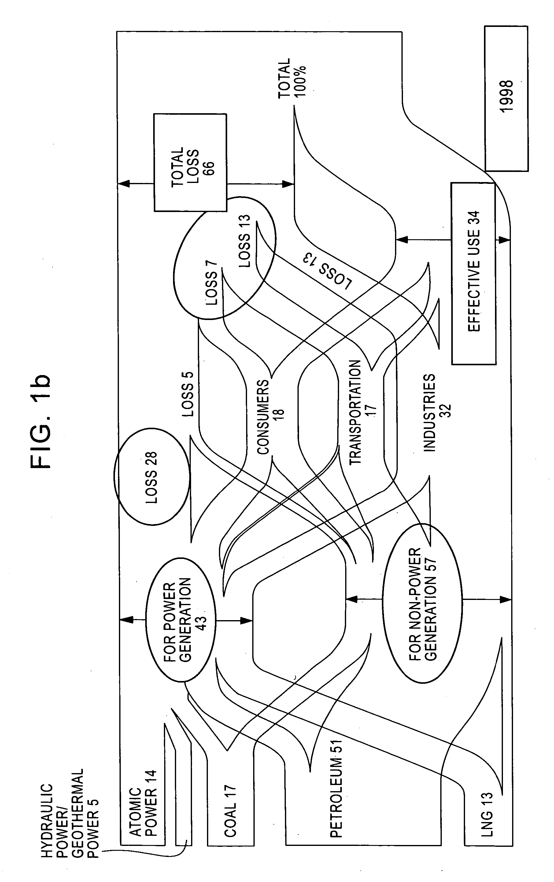
TECHNICAL FIELD [0001] The present invention relates to a method of supplying energy for supplying energy within a virtual area wherein a plurality of energy-consuming devices are provided (hereinafter referred to as “energy supply and demand grid”) and a system therefor. BACKGROUND ART [0002] In Japan, energy consumption by consumers and transportation has been increasing more than energy consumption by industries. One of the reasons for this is a systematic difference in energy use. For example, in factories, elements such as generation (purchase), distribution, and consumption of energy and the entire use of energy have been optimized in the pursuit of economical efficiency. In contrast, in the case of consumers and transportation, energy is used for various segmentized purposes, and the top priority is often given to convenience. Thus, it has been difficult to manage energy using a unified system and to meet excessive energy demand with surplus unutilized energy. [0003] As shown...

Claims


Application Information

Patent Timeline
IPC IPC(8): F02C3/20
CPCC01B3/323C01B2203/0233C01B2203/0238Y02T10/16C01B2203/141F02M37/0064Y02E20/14C01B2203/0475Y02P20/129Y02P20/133Y02T10/12
Inventor NAKAGAWA, TSUGUHIKOTSUYUGUCHI, TETSUOOGURA, YASUTSUGU
Owner JFE R&D
Learn More