
Information recording apparatus for thermosensitive medium

Inactive Publication Date: 2007-11-22
TOSHIBA TEC KK
View PDF1 Cites 6 Cited by
  • Summary
  • Abstract
  • Description
  • Claims
  • Application Information

AI Technical Summary

Benefits of technology

[0008]An object of the present invention is to provide an economically more efficient and down-sized information recording apparatus capable of realizing a sufficient recording speed by using a relatively low output light source.

Problems solved by technology

Therefore, a recording speed obtained in using a line-type thermal head cannot be realized.
However, in this method, there is a problem that an expensive and large-sized recording apparatus must be used.

Method used


Image

  • Information recording apparatus for thermosensitive medium
  • Information recording apparatus for thermosensitive medium
  • Information recording apparatus for thermosensitive medium

Examples


first embodiment

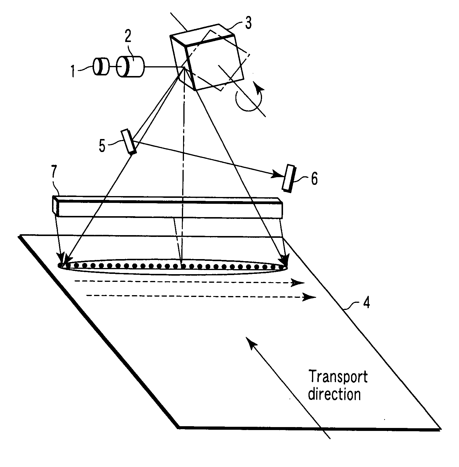
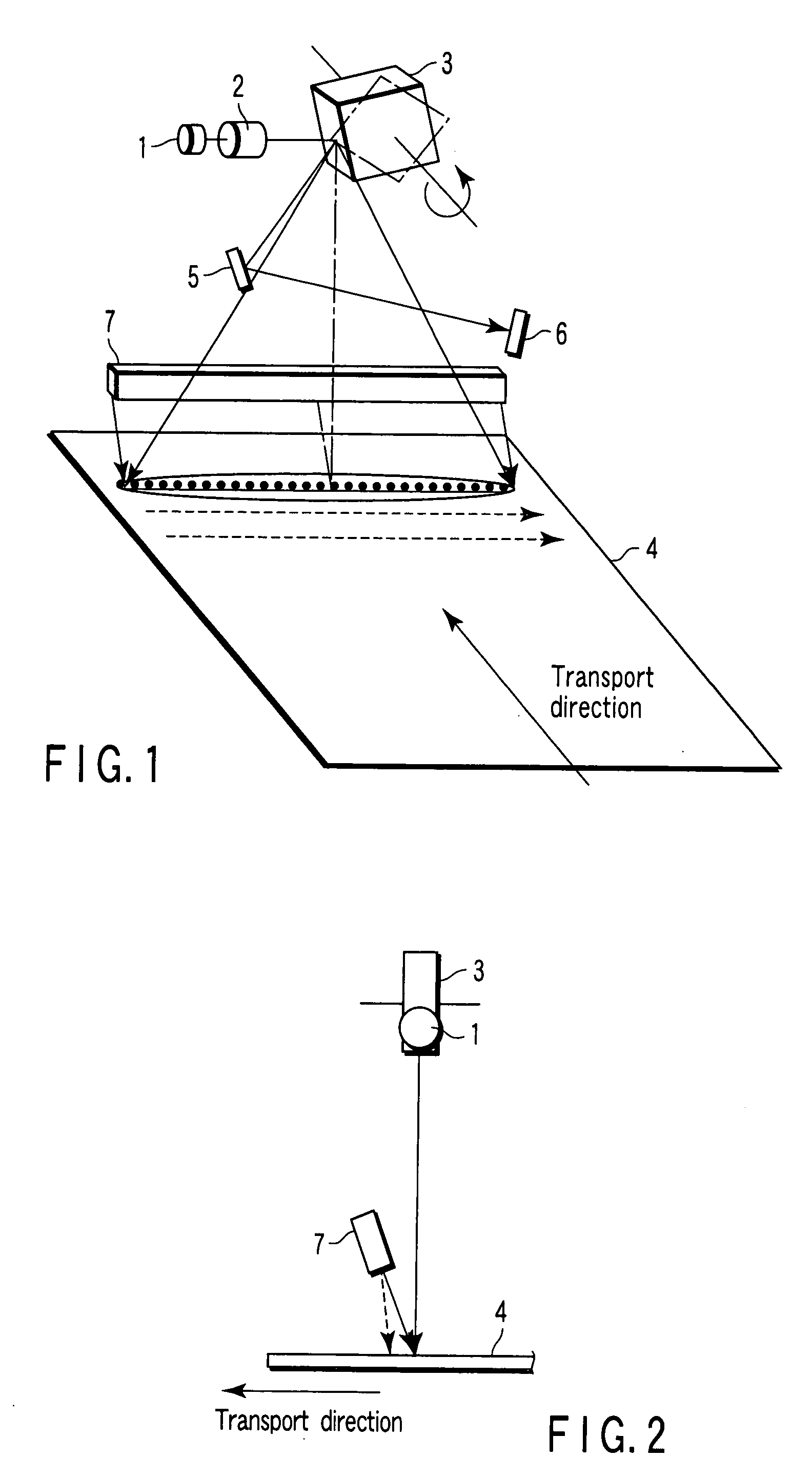
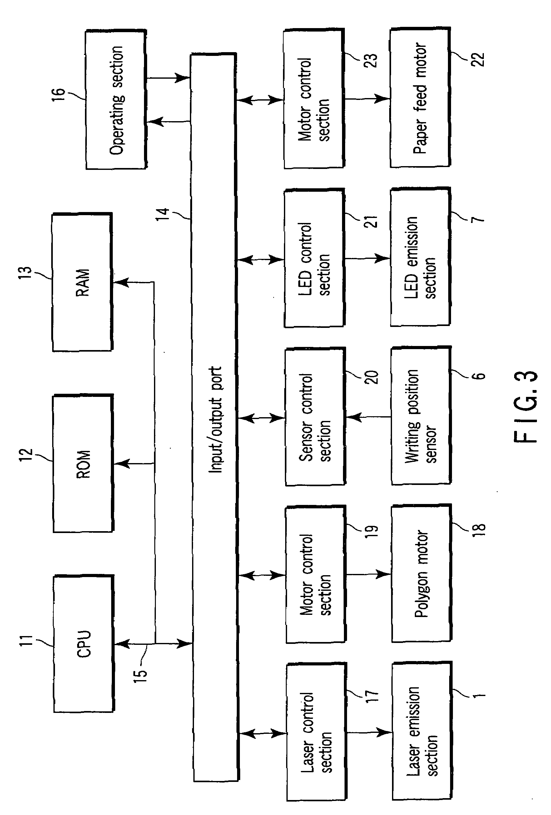
[0030]First, a first embodiment in which a pair of a laser emission section and an LED emission section is arranged will be described.

[0031]FIG. 1 is a perspective view showing a main section configuration of a recording apparatus according to the first embodiment of the present invention. The recording apparatus is provided with a laser emission section 1 as a first light source. A laser beam from the laser emission section 1 is irradiated via a collimator 2 to a polygon mirror 3. The laser emission section 1 is composed of a commercially available semiconductor laser of an output of several watts having an emission wavelength λ1 in the near-infrared (750 to 1,000 nm).

[0032]The collimator 2 converts the laser beam as the divergent light into parallel luminous fluxes. The laser emission section 1 has a high calorific power. Thus, the laser emission section 1 is fixed to a heat slinger so as to radiate generated heat.

[0033]The polygon mirror 3 is driven to rotate by a polygon motor d...

second embodiment

[0053]Now, a second embodiment in which a plurality of pairs of laser emission sections and LED emission sections are arranged will be described.

[0054]FIG. 10 is a perspective view showing a main section configuration of a recording apparatus in a second embodiment of the present invention. In the recording apparatus, there are arranged, as a first light source, five laser emission sections 31, 32, 33, 34 and 35 with a predetermined pitch P0 in the transport direction of the thermosensitive medium 4, each of the laser emission sections 31, 32, 33, 34 and 35 having a semiconductor laser and a collimator. The semiconductor laser is a commercially available one of an output of several watts having an emission wavelength in the near-infrared (750 to 1000 nm). The laser beams from the respective laser emission sections 31 to 35 are irradiated to the polygon mirror 36.

[0055]The arrangement pitch P0 of the respective laser emission sections 31 to 35 is a printing pitch P1 as it is in the t...


PUM


Abstract

A recording apparatus for recording information in a thermosensitive medium which has a photothermal conversion layer having a light wavelength absorption property and a coloring layer colored by the heat generated by the photothermal conversion layer comprises a first light source that emits a light beam for writing information to a scanning position in a main scanning direction in the thermosensitive medium, and a second light source that emits a light of lower energy density than the light beam emitted by the first light source to the scanning position in the main scanning direction in the thermosensitive medium or to the vicinity thereof. The first light source and the second light source emit lights having wavelengths within the range of the absorption property of the photothermal conversion layer respectively to form recording dots of one line in the main scanning direction in a noncontact manner with the thermosensitive medium.

Description

CROSS-REFERENCE TO RELATED APPLICATIONS[0001]This application is based upon and claims the benefit of priority from prior Japanese Patent Applications No. 2006-140367, filed May 19, 2006; and No. 2007-062848, filed Mar. 13, 2007, the entire contents of both of which are incorporated herein by reference.BACKGROUND OF THE INVENTION[0002]1. Field of the Invention[0003]The present invention relates to an apparatus for recording information in a thermosensitive medium by a combination of dots.[0004]2. Description of the Related Art[0005]Thermosensitive media include a recording medium capable of thermal recording and a rewritable medium capable of thermal recording and thermal erasing. Conventionally, for recording media, there are known recording apparatuses using thermosensitive materials such as leuco dye systems and diazo compound systems. Conventionally, for a rewritable medium, there are known recording apparatuses using reversible thermal recording materials capable of repeating c...

Claims


Application Information

Patent Timeline
IPC IPC(8): B41J2/455
CPCB41J2/471B41J2/4753B41J2/473
Inventor MURAKAMI, KAZUNORIOHTAKA, YOSHIMITSUTAMURA, TOSHIYUKIHIYOSHI, TAKAYUKI
Owner TOSHIBA TEC KK
Learn More