
Mitigation of in-tube fouling in heat exchangers using controlled mechanical vibration

Inactive Publication Date: 2007-11-22
EXXON RES & ENG CO
View PDF18 Cites 59 Cited by
  • Summary
  • Abstract
  • Description
  • Claims
  • Application Information

AI Technical Summary

Benefits of technology

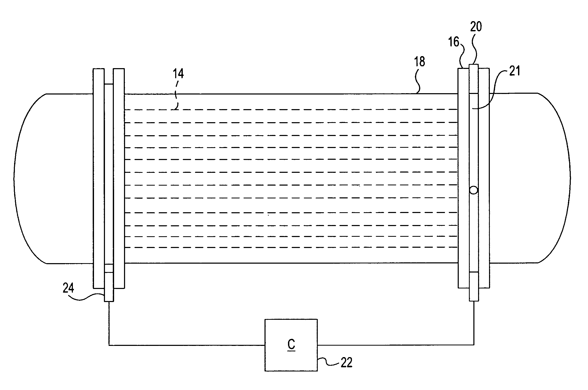
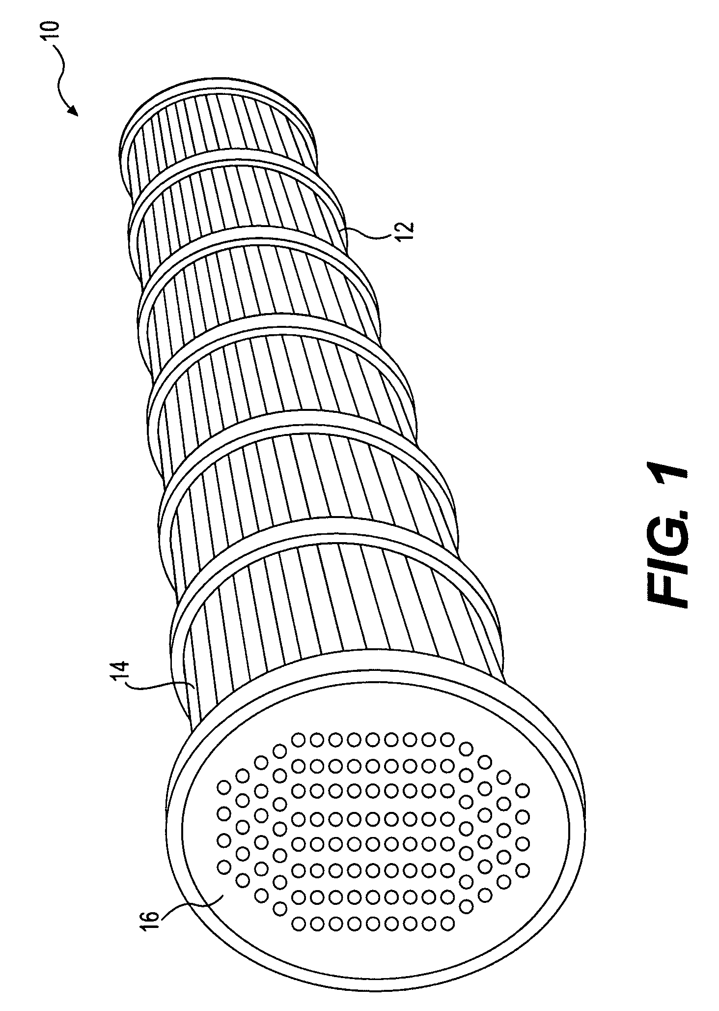
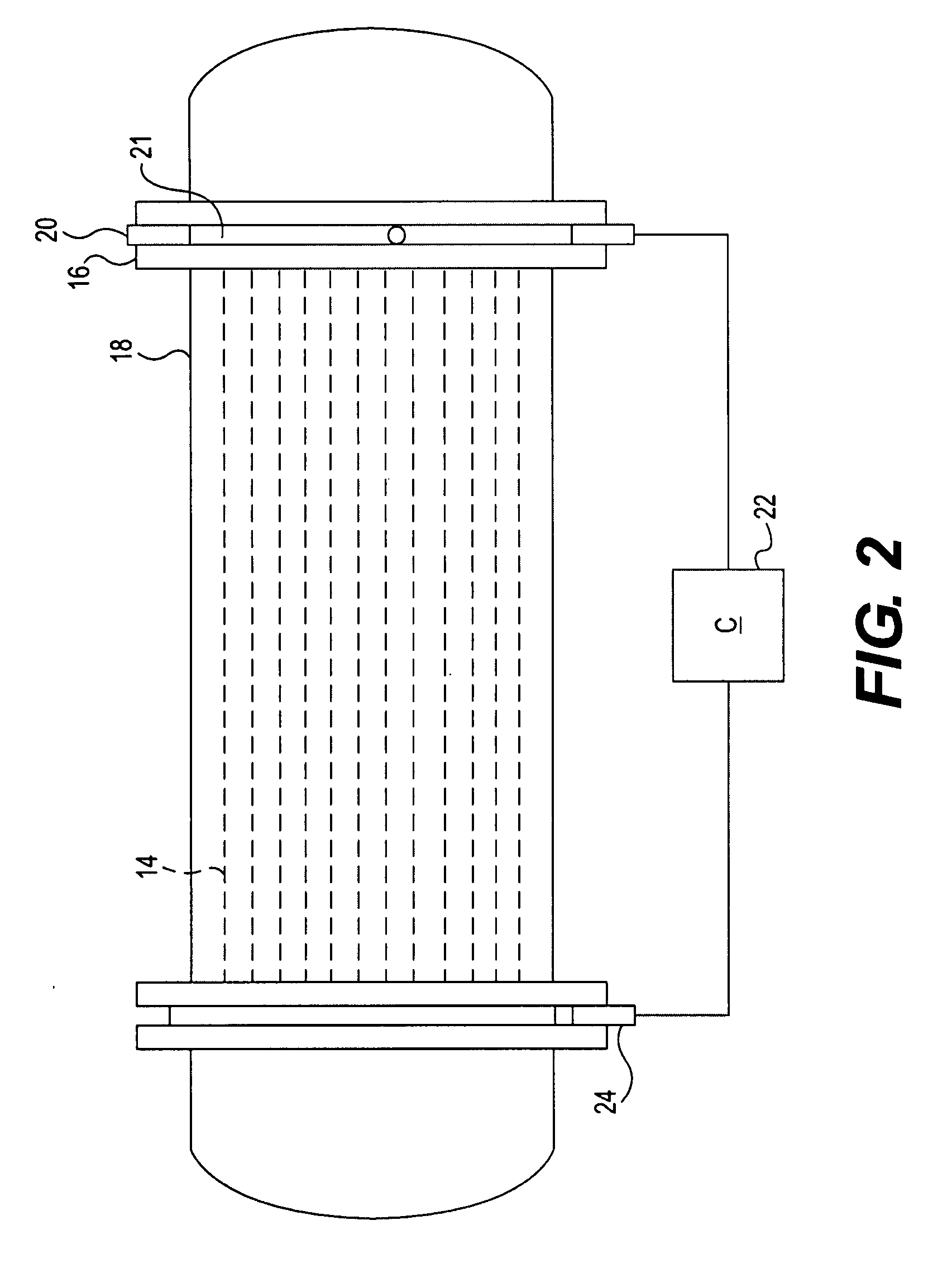
[0015]These and other aspects can be realized by the present invention, which is directed to a process for reducing fouling in a heat exchanger, comprising the steps of providing a heat exchanger with tubes for liquid flow and a fixed mounting element that supports the tubes, and applying a mechanical force to the fixed mounting element to induce a vibration in the tubes that causes shear motion in the liquid flowing adjacent to the tubes to reduce fouling of the tubes.

Problems solved by technology

In petroleum processing, fouling is the accumulation of unwanted hydrocarbonbased deposits on heat exchanger surfaces.
It has been recognized as a nearly universal problem in design and operation of refining and petrochemical processing systems, and affects the operation of equipment in two ways.
First, the fouling layer has a low thermal conductivity.
This increases the resistance to heat transfer and reduces the effectiveness of the heat exchangers—thus increasing temperature in the system.
Second, as deposition occurs, the cross-sectional area is reduced, which causes an increase in pressure drop across the apparatus and creates inefficient pressure and flow in the heat exchanger.
Heat exchanger in-tube fouling costs petroleum refineries hundreds of millions of dollars each year due to lost efficiencies, throughput, and additional energy consumption.
With the increased cost of energy, heat exchanger fouling has a greater impact on process profitability.
Petroleum refineries and petrochemical plants also suffer high operating costs due to cleaning require as a result of fouling that occurs during thermal processing of whole crude oils, blends and fractions in heat transfer equipment.
While many types of refinery equipment are affected by fouling, cost estimates have shown that the majority of profit losses occur due to the fouling of whole crude oils and blends in pre-heat train exchangers.
One of the more common root causes of rapid fouling, in particular, is the formation of coke that occurs when crude oil asphaltenes are overexposed to heater tube surface temperatures.
Heat exchanger fouling forces refineries to frequently employ costly shutdowns for the cleaning process.
However, off-line cleaning interrupts service.
This can be particularly burdensome for small refineries because there will be periods of non-production.
This assembly requires a specialized resilient mounting assembly however and could not be easily adapted to an existing heat exchanger.
Again, this system requires a specialized mounting assembly for the individual ducts in a heat exchanger that would not be suitable for an existing system.

Method used


Image

  • Mitigation of in-tube fouling in heat exchangers using controlled mechanical vibration
  • Mitigation of in-tube fouling in heat exchangers using controlled mechanical vibration
  • Mitigation of in-tube fouling in heat exchangers using controlled mechanical vibration

Examples


Embodiment Construction

[0032]This invention is directed to a method of mitigating fouling in heat exchangers, in general, and the devices for practicing the method. In a preferred use, the method and devices are applied to heat exchangers used in refining processes, such as in refineries or petrochemical processing plants. The invention is particularly suited for retrofitting existing plants so that the process may be used in existing heat exchangers, especially while the heat exchanger is on line and in use. Of course, it is possible to apply the invention to other processing facilities and heat exchangers, particularly those that are susceptible to fouling in a similar manner as experienced during refining processes and are inconvenient to take off line for repair and cleaning.

[0033]While this invention can be used in existing systems, it is also possible to initially manufacture a heat exchanger with the vibration inducing devices described herein and use the method in accordance with this invention in...


PUM


Abstract

Fouling of heat exchange surfaces is mitigated by a process in which a mechanical force is applied to a fixed heat exchanger to excite a vibration in the heat exchange surface and produce shear waves in the fluid adjacent the heat exchange surface. The mechanical force is applied by a dynamic actuator coupled to a controller to produce vibration at a controlled frequency and amplitude output that minimizes adverse effects to the heat exchange structure. The dynamic actuator may be coupled to the heat exchanger in place and operated while the heat exchanger is on line.

Description

BACKGROUND OF THE INVENTION[0001]1. Field of the Invention[0002]This invention relates to heat exchangers used in refineries and petrochemical plants. In particular, this invention relates to mitigation of fouling in heat exchangers.[0003]2. Discussion of Related Art[0004]Fouling is generally defined as the accumulation of unwanted materials on the surfaces of processing equipment. In petroleum processing, fouling is the accumulation of unwanted hydrocarbonbased deposits on heat exchanger surfaces. It has been recognized as a nearly universal problem in design and operation of refining and petrochemical processing systems, and affects the operation of equipment in two ways. First, the fouling layer has a low thermal conductivity. This increases the resistance to heat transfer and reduces the effectiveness of the heat exchangers—thus increasing temperature in the system. Second, as deposition occurs, the cross-sectional area is reduced, which causes an increase in pressure drop acros...

Claims


Application Information

Patent Timeline
IPC IPC(8): F28G7/00
CPCF28D7/16F28G7/00F28F19/00F28D2021/0059
Inventor SONG, LIMINLOBO, JULIO D.BRONS, GLEN B.CHHOTRAY, SANJOSHI, HIMANSHU M.LUTZ, GEORGE A.
Owner EXXON RES & ENG CO
Learn More