
Method and system for rapid modeling and verification of excitation systems for synchronous generators

a technology of excitation system and synchronous generator, applied in adaptive control, process and machine control, instruments, etc., can solve the problems of time-consuming, expensive and error-prone multi-step process, and repeated repetition

Active Publication Date: 2007-11-08
GENERAL ELECTRIC CO
View PDF14 Cites 9 Cited by
  • Summary
  • Abstract
  • Description
  • Claims
  • Application Information

AI Technical Summary

Benefits of technology

[0013] A system has also be developed for producing frequency response data from a generator system comprising: applying a perturbing signal to a signal input of an exciter system for a synchronous generator; collecting data regarding signal output from multiple signal points in the exciter system; transforming the collected data to predict a signal response at a signal output in the system different from the signal points used for collecting the data; producing multiple frequency response data using a single test to reduce test time and thus the time a generator is subject to perturbing events; using frequency response measurements for IEEE model validation.

Problems solved by technology

If the collected data was found in error, the testing may have had to been repeated which required an additional visit to the customer site.
In the past, the data recording, analysis, and reporting systems were not fully integrated with the excitation system and its configuration tools.
This multi-step process has been time consuming, expensive and error prone.

Method used


Image

  • Method and system for rapid modeling and verification of excitation systems for synchronous generators
  • Method and system for rapid modeling and verification of excitation systems for synchronous generators
  • Method and system for rapid modeling and verification of excitation systems for synchronous generators

Examples


Embodiment Construction

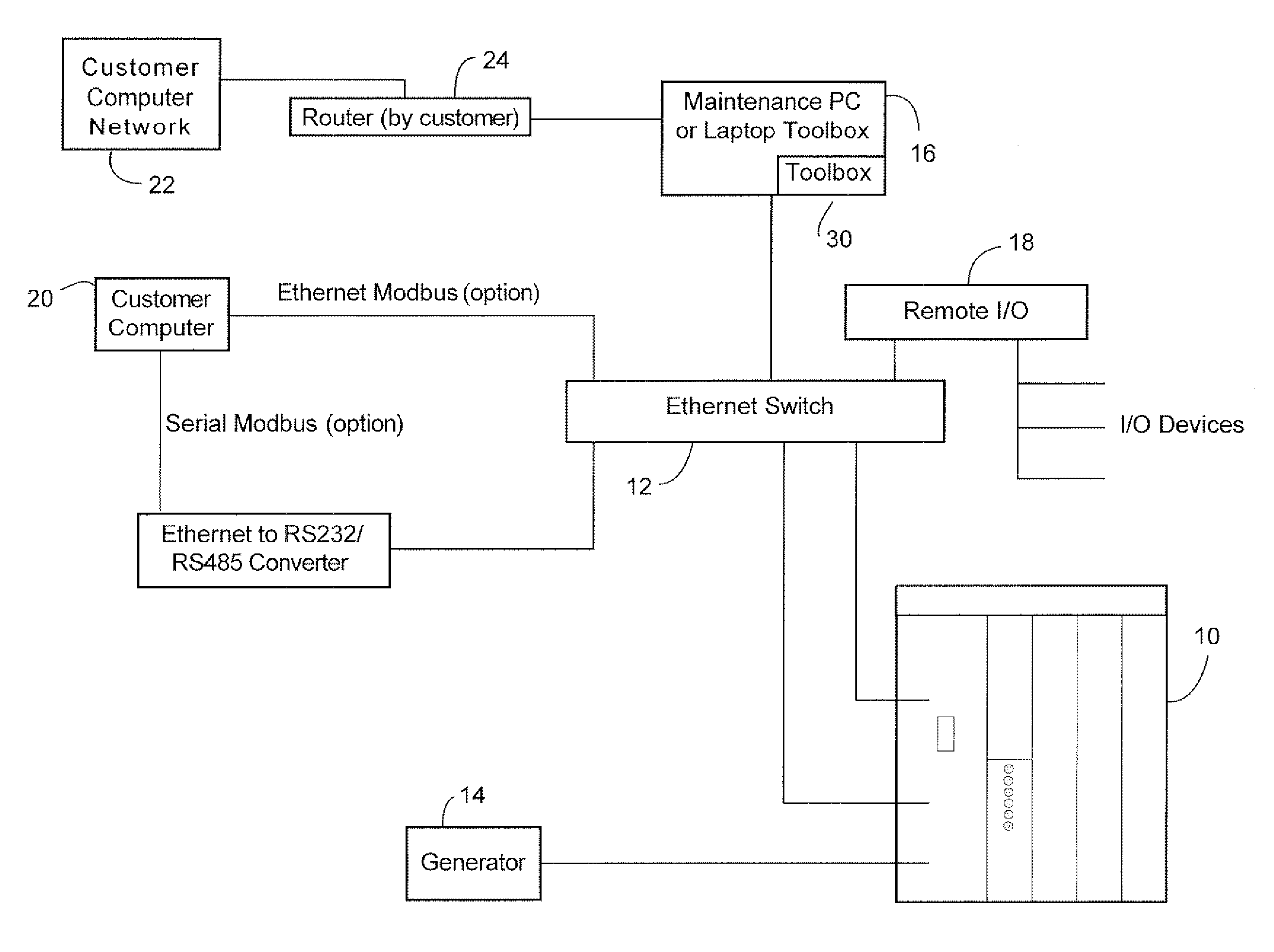
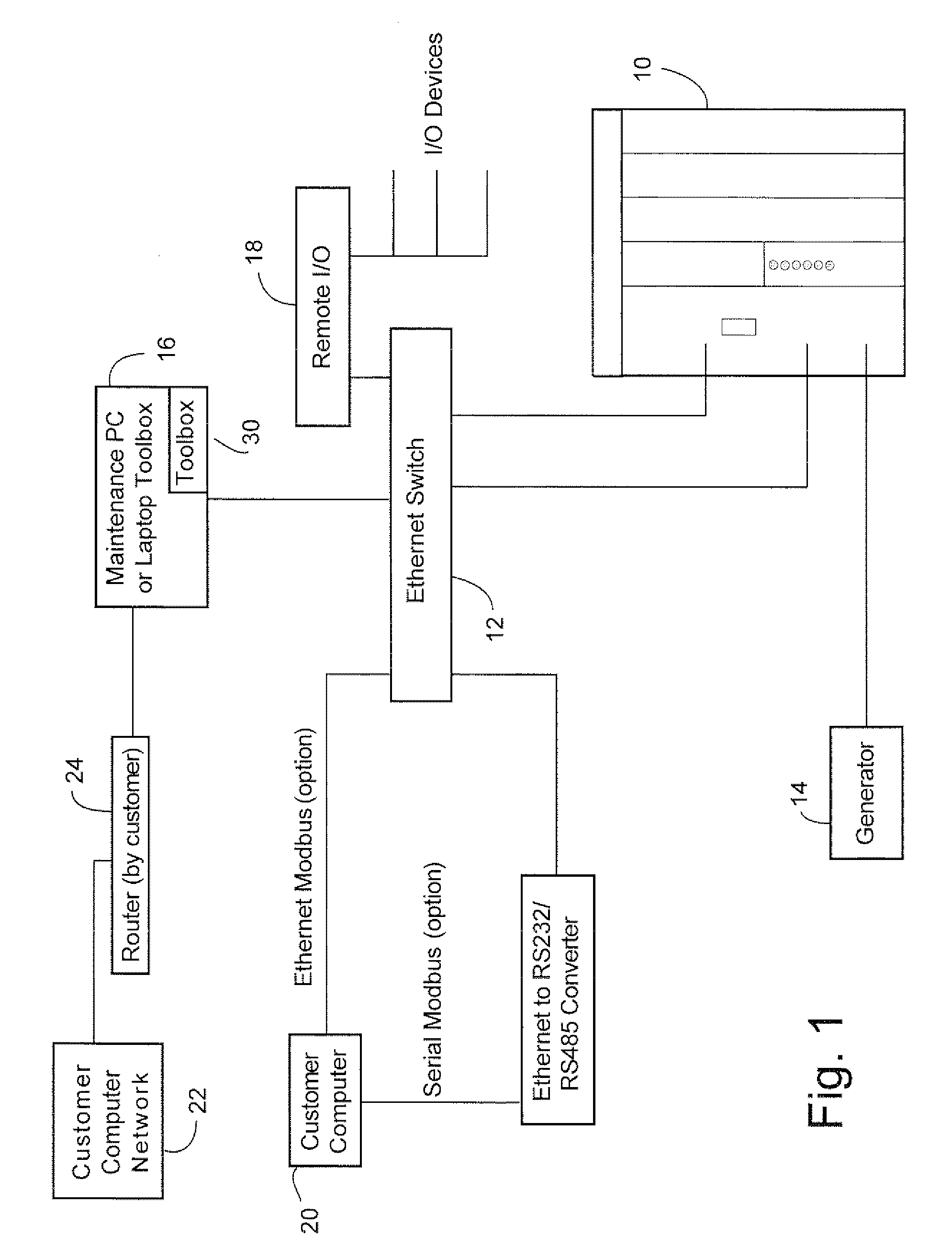
[0018] Software programs have been developed that may be incorporated in the computer(s) for exciter control hardware and in an attached maintenance computer (e.g. a PC running Microsoft Windows™). The exciter control hardware may be otherwise conventional, such as a General Electric Company EX2100™ exciter, but should for practical reasons be digital in nature for data collection purposes and tuning. The EX2100 exciter performs all control functions, such as regulator and limiter functions, for an excitation system of an industrial or power utility electrical synchronous generator. The attached maintenance computer performs analytical and reporting functions regarding the excitation system. The EX2100 exciter can operate without the maintenance computer being attached and does so during much of the normal operation of the generator. The maintenance computer transmits configuration information to the exciter control and receives data from the exciter control.

[0019]FIG. 1 is a diagr...


PUM


Abstract

A method for modeling an excitation system for a synchronous electrical power generator including: selecting a standard mathematical excitation system model from a plurality of standard excitation system models stored electronically; wherein the selected standard model is selected based on a similarity to the excitation system and can be an IEEE standard model; collecting data from the excitation system; determining parameter settings for the selected standard model using first pre-calculated and then collected (measured) data; verifying the selected standard model with tailored parameter settings by comparing an output of the model to a corresponding output of the excitation system; storing electronically the verified selected standard model with tailored settings; generating a report of the verified selected standard model with the tailored settings; performing rapidly and automatically model generation from a maintenance computer proximate to the excitation system; performing rapidly and automatically model generation without the need for system experts or extra equipment; and providing means to repeat test an operating excitation system at low cost and risk

Description

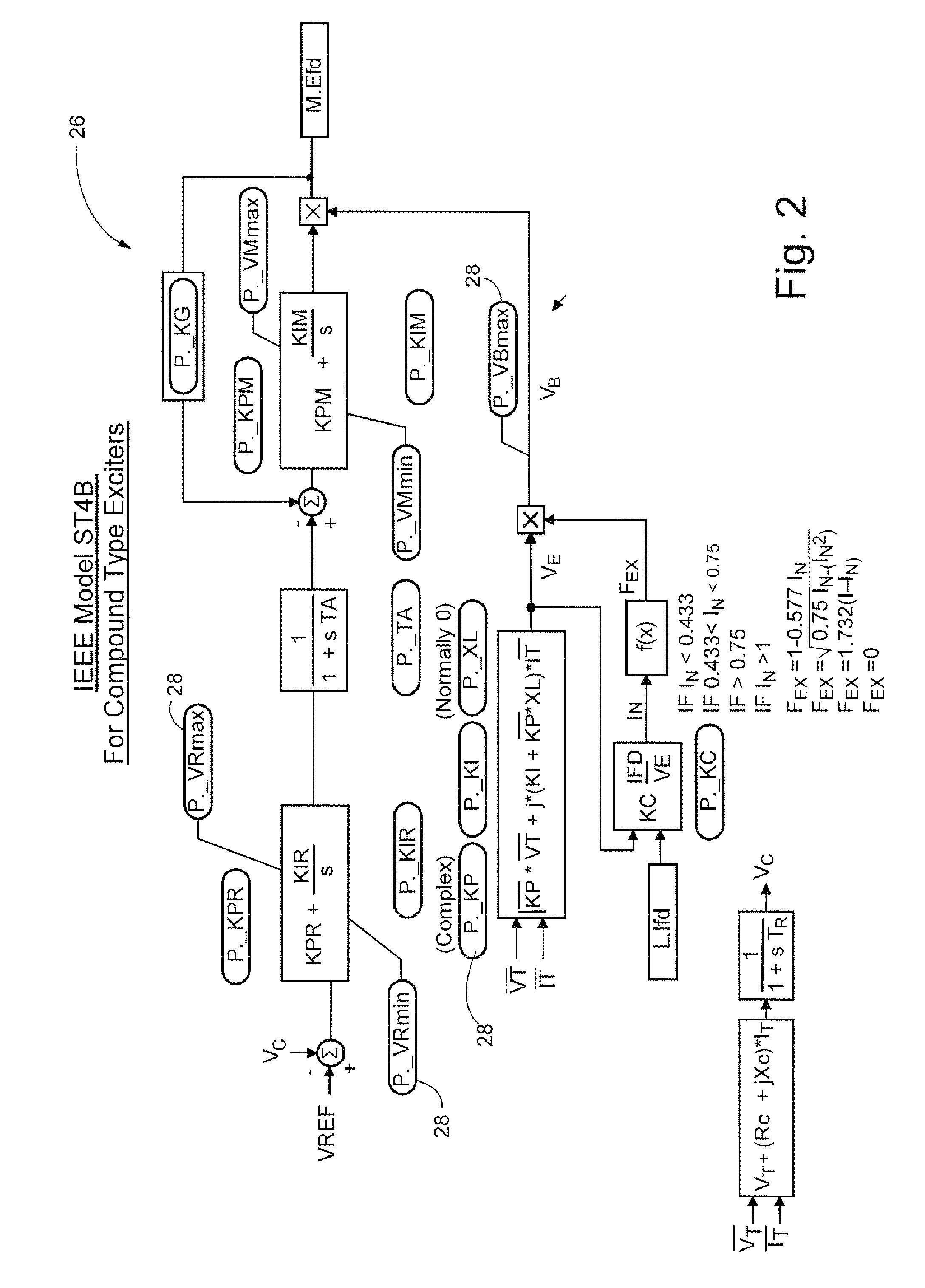
BACKGROUND OF THE INVENTION [0001] This invention relates generally to excitation systems for synchronous generators. In particular, the invention relates to modeling of excitation systems. [0002] Excitation systems are used to produce a dominant magnetic flux in synchronous generators. Synchronous generators typically have a controller for their excitation systems. It is common practice in the industry to produce a tailored IEEE (Institute of Electrical and Electronics Engineers, Inc.) model of the excitation system of a particular industrial generator. [0003] Various generic excitation models have been endorsed by IEEE committees as standard models for use in modeling specific excitation systems. Each of these standard models is a simplified control block diagram with parameters that can be tailored to mathematically match the response of a particular excitation system to certain data inputs. Each model has certain parameters: variables and constants. The constants can be set to t...

Claims


Application Information

Patent Timeline
Patent Type & Authority Applications(United States)
IPC IPC(8): G05B13/02
CPCG06F17/5036G05B17/02G06F30/367
Inventor PEARSON, WILLIAM ROBERTMONCLOVA, PEDROZELEZNIK, JAMES WILLIAM
Owner GENERAL ELECTRIC CO
Learn More