
Bush bearing with bearing body having an axial profile

a bush bearing and bearing body technology, applied in the direction of elastic bearings, bearing unit rigid support, shock absorbers, etc., can solve the problems of reducing the service life and stability of the bearing, and achieve the effect of avoiding adversely affecting its stability and service li

Inactive Publication Date: 2007-11-08
ZF FRIEDRICHSHAFEN AG
View PDF9 Cites 17 Cited by
  • Summary
  • Abstract
  • Description
  • Claims
  • Application Information

AI Technical Summary

Benefits of technology

[0007]It is therefore an object of the invention to form a bush bearing with a bearing body capped by axial flanges such that the bearing body is capable of supporting high radial loads without adversely affecting its stability and service life.
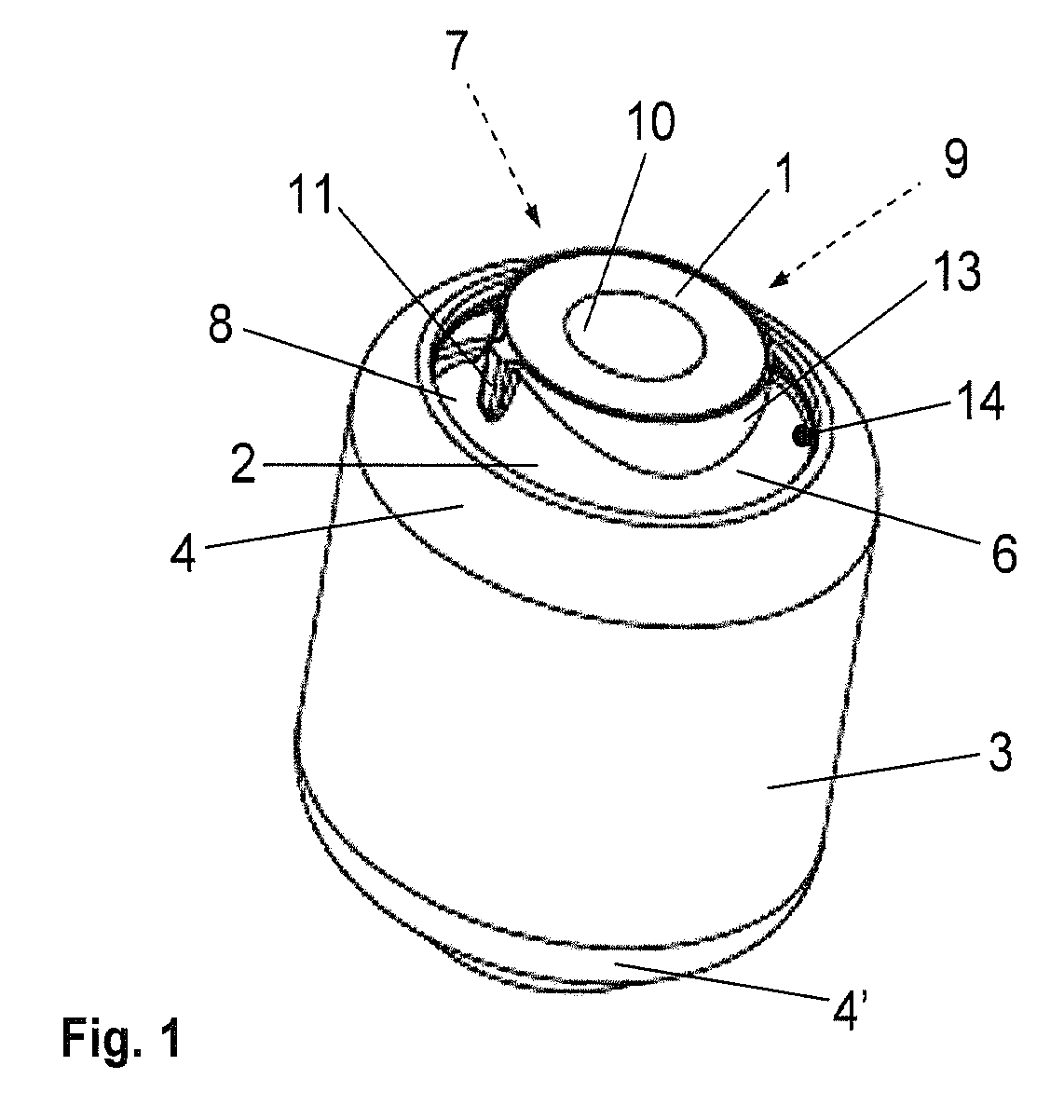
[0009]The proposed elastomer bush bearing includes, as is generally known, a metallic inner part with a circular or elliptical cross-sectional area and a through opening extending in the axial direction through the inner part, a cylindrical outer sleeve surrounding the inner part, and an elastomer bearing body disposed between the inner part and the outer sleeve and adheringly connected at least with the inner part by vulcanization. The inner part can be formed, for example, as a cold-extruded steel, or aluminum part or can be produced from an extruded tube, or can be a diecast aluminum part. The outer sleeve is preferably also metallic, i.e., made of aluminum or steel, but can optionally also be made of plastic. The outer sleeve has on each of its axial ends a circumferential flange oriented toward the inner part. In this way, the bearing body is encapsulated which makes the bearing suitable for supporting high axial loads.
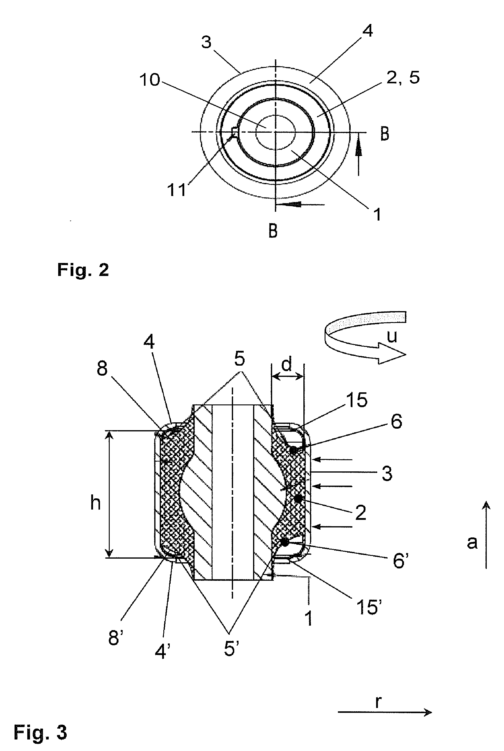
[0011]With the design of the bearing according to the invention, the elastomer is able to yield to the applied high radial loads in the axial direction, i.e., in the direction of the respective flange, in the region of the wave troughs, which during proper installation of the bearing coincide with the main radial load bearing direction, without expanding from the outer sleeve of the bearing out of the flange edge. This prevents the expanded material of the bearing body from being sheared off at the flange edge, which can decrease the service life of the bearing. It is therefore possible to realize bearings which have a decreased radial stiffness with an only slightly changed bearing geometry and an almost identical axial stiffness, without adversely affecting the stability or the service life, or more particularly the radial load bearing capacity.
[0012]According to an advantageous embodiment, the bearing has an inner part with a circular cross-sectional area, wherein the end faces of its elastomer bearing body have a sinusoidal contour by forming two wave troughs and wave crests extending in the same direction and / or with the same phase. It should also be mentioned that a contour extending in the same directions does not necessarily imply that the wave troughs and wave crests each have identical depth or identical height with respect to the radial material thickness of the bearing body or when comparing the two radial end faces. It only implies that in a circumferential region, where a wave trough is formed on the outer surface of the bearing body contacting the inner surface of the bearing sleeve, a trough is also formed on the inner surface of the bearing a body contacting the inner part. The same applies to the identical circumferential segment on the opposite axial end face. The inner part of the bearing of the invention is preferably formed essentially as a cylinder. Because the aforedescribed design of the bearing is not intended to achieve a radial stiffness that varies in the circumferential direction, the inner part can have different shapes that compensate at least partially differences in the radial stiffness due contouring of the bearing body on the end side in the circumferential direction. In another similar embodiment with an inner part, distribution of the stress generated in the elastomer during loading is improved by expanding the outside contour to form a bulge in an axial center section, either in a circumferential segment or across the entire circumference. Advantageously, the axial stiffness is also affected positively. The bulge-shaped expansion of the outer contour of the bearing body, i.e., a segment-wise increase in the outside diameter, can be implemented, for example, by spraying a plastic material around the respective region.
[0013]A radial stiffness which remains approximately constant over the entire circumference of the bearing, can also be attained by forming the elastomer bearing body of different elastomer materials. In a corresponding embodiment of the bearing of the invention, spray-on points for spraying on different materials are provided on the outer surface of the inner part in the region of the waves troughs and wave crests. The materials are hereby selected so that the material sprayed on in the region of the wave crests, when the radial stiffness of the bearing body is already small, has a smaller basic stiffness than the elastomer material used in the region of the wave troughs. This is indicated, in particular, when significantly lower loads are expected in the secondary load direction, which coincides with the wave crests, than in the main load direction, which also eliminates the risk that the elastomer expands to the outside.
[0014]According to an advantageous modification of the bearing of the invention, means are formed on the bearing for marking its respective position with respect to the circumference. This provides a positioning aid for mounting the bearing in an automobile and / or its temporal installation by a mounting device. This guarantees proper orientation of the bearing during installation, so that the wave troughs formed on the end faces of the bearing body are arranged in the main load direction.

Problems solved by technology

However, as long as the bearing is still subjected to high radial loads, there is still a risk that the bearing body, or the rubber body, expands partially across the flange out of the bearing body, allowing the expanding material to be sheared off at the flange under the load.
This disadvantageously reduces the service life and stability of the bearing.

Method used


Image

  • Bush bearing with bearing body having an axial profile
  • Bush bearing with bearing body having an axial profile
  • Bush bearing with bearing body having an axial profile

Examples


Embodiment Construction

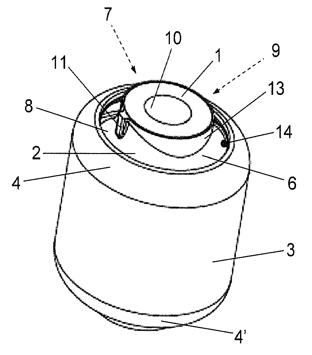
[0021]FIG. 1 shows a three-dimensional diagram of a possible embodiment of the bearing according to the invention. The bearing includes, as described above, the metallic inner part 1, the outer sleeve 3 concentrically surrounding the inner part 1, and the elastomer bearing body 2 arranged between the inner part 1 and the outer part 3. It will be assumed for the depicted bearing that its inner part 1 is, for example, a cold-extruded steel part which is concentrically surrounded by an outer sleeve 3 made of steel, wherein the elastomer bearing body 2 disposed between the inner part 1 and the outer sleeve 3 is adheringly connected with both the inner part 1 and the outer sleeve 3 by vulcanization. As described above, the inner part 1 and the outer sleeve 3 can also be made of other materials, whereby an adherent connection need not exist between the bearing body 2 and the outer sleeve 3. In any event, the outer sleeve is flanged on both sides by forming respective inwardly oriented fla...


PUM


Abstract

An elastomer bush bearing, wherein the bearing body (2) is encapsulated through axial flanges (4, 4′) of the outer bearing sleeve (3), with the bush bearing having an elastomer bearing body (2) with a special profile in the axial direction. The bearing body (2) is employed in constructing the bush bearing of the invention, which is capable of supporting high radial loads even with low radial stiffness and without adversely affecting its stability and service life. The two axial end faces (5, 5′) of the bearing body (1) each have undulated contours which extend in the circumferential direction (u) in the same direction, both with respect to one another and also over the entire region of the material thickness (d) of the bearing body (2). The end faces (5, 5′) of the bearing body (2) thus have wave troughs (6, 6′, 7, 7′) and wave crests (8, 8′, 9, 9′), whereby the corresponding wave troughs (6, 6′, 7, 7′) of both end faces (5, 5′) and their wave crests (8, 8′, 9, 9′) are formed so as to face one another, and each extend radially over the entire material thickness (d) of the bearing body (2) in the respective circumferential segment.

Description

BACKGROUND OF THE INVENTION[0001]1. Field of the Invention[0002]The present invention relates to an elastomer bush bearing according to the preamble of the independent claim. More particularly, the invention relates to a bush bearing, wherein the bearing body is encapsulated by axial flanges of the outer sleeve of the bearing and wherein the bush bearing has an elastomer bearing body with a particular profile extending in the axial direction.[0003]2. Description of the Related Art[0004]Elastomer bush bearings, which are employed frequently in the automotive engineering for supporting chassis components, consist essentially of a cylindrical or tubular metallic inner part, an elastomer bearing body which concentrically surrounds the inner part, and an outer sleeve receiving the inner part with the bearing body. The elastomer bearing body, for example, a rubber spring, is generally adheringly connected at least with the inner part by vulcanization. In several embodiments of correspondi...

Claims


Application Information

Patent Timeline
IPC IPC(8): F16C27/06
CPCF16F1/387F16F1/3863
Inventor SIEMER, HUBERTFRANKE, TIM-MALTEHOPING, CLAUDIA
Owner ZF FRIEDRICHSHAFEN AG
Learn More