
Motor

A front bearing and shaft technology, applied in electrical components, electromechanical devices, electric components, etc., can solve the problems of increased machine size, machine weight, volume, energy consumption, etc., to achieve increased radial load, large radial The effect of carrying capacity

Pending Publication Date: 2019-10-11
伏为电机(广州)有限公司
View PDF0 Cites 0 Cited by
  • Summary
  • Abstract
  • Description
  • Claims
  • Application Information

AI Technical Summary

Problems solved by technology

[0003] With the development of machinery and equipment in the direction of miniaturization, light weight, and flexibility and the continuous improvement of control accuracy requirements, more and more industrial equipment has begun to use DD motors. In some applications, equipment manufacturers In order to improve the control of equipment Accuracy and response speed, began to try to use DD motors directly as the fourth and fifth axes of 5-axis machining equipment, in a typical machining process, compared with traditional DD motor applications, the fourth and fifth axes need to bear Larger radial loads, in many cases, need to use a DD motor with a larger frame size to meet the application requirements, but it will lead to an increase in the size of the machine, and because the fifth axis motor is actually the fourth axis motor As part of the overall load, once the fifth axis motor is increased, it is necessary to further increase the torque output capacity and load bearing capacity of the fourth axis, which leads to a vicious circle. The final result is the weight, volume, and energy consumption of the machine. sharp rise

Method used


Image

  • Motor
  • Motor

Examples


Embodiment Construction

[0018] The present invention will be further described below in conjunction with the accompanying drawings. It should be noted that the following examples are based on the premise of this technical solution, and provide detailed implementation and specific operation process, but the protection scope of the present invention is not limited to the present invention. Example.

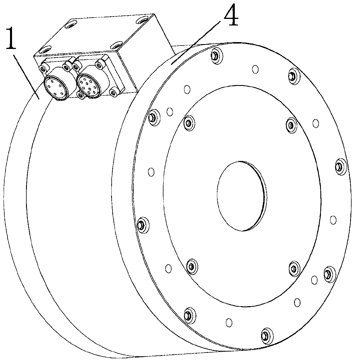
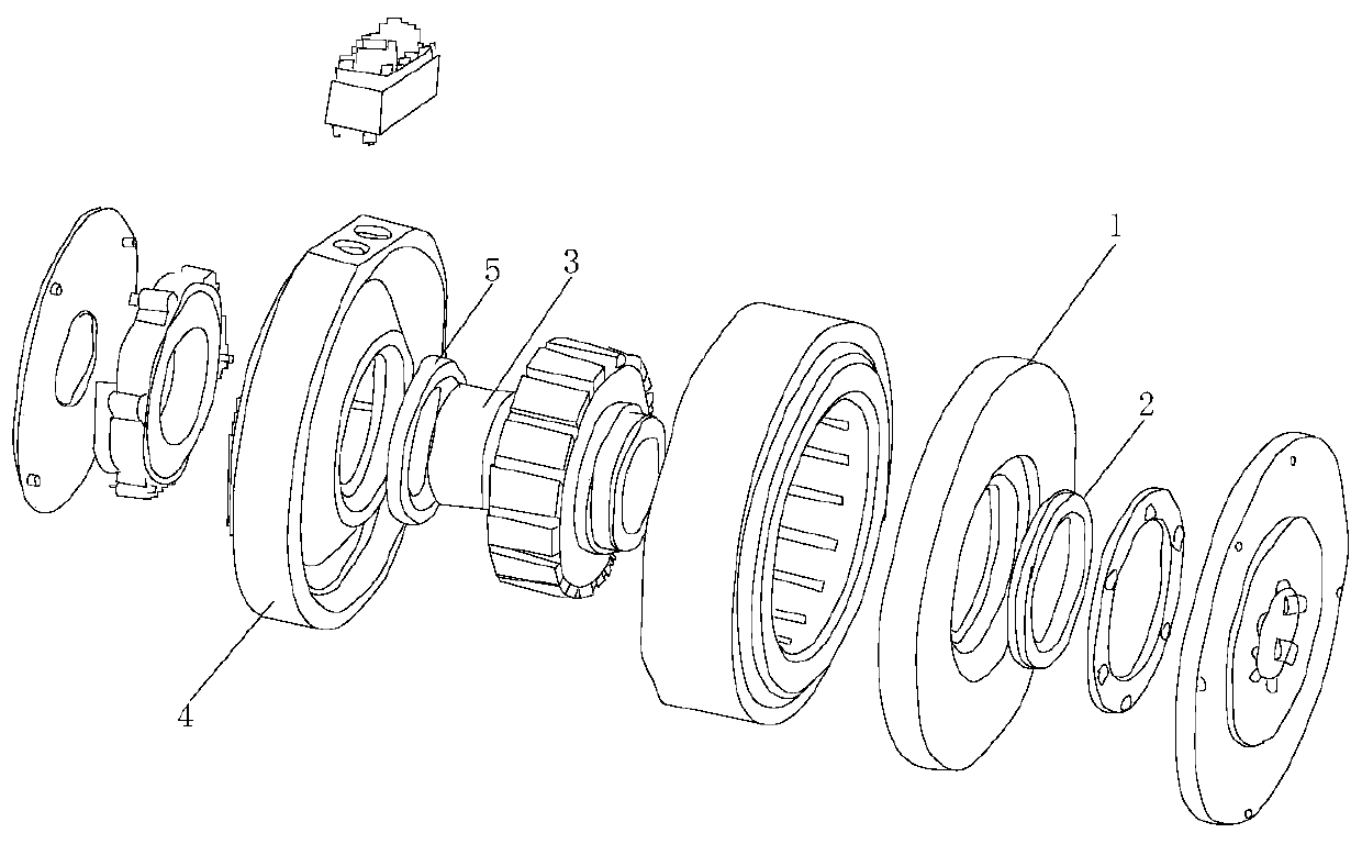
[0019] A motor, comprising a front end cover 1, a front bearing 2, a rotating shaft 3, a rear end cover 4 and a rear bearing 5, the outer ring of the front bearing 2 is fixed inside the bearing chamber of the front end cover 1, the inner ring of the front bearing 2 and the rotating shaft 3 The outer ring of the rear bearing 5 is fixed inside the bearing chamber of the rear end cover 4, and the inner ring of the rear bearing 5 is connected with the outer ring of the rotating shaft 3; load, front end cover 1, front bearing 2, rear end cover 4 The load, the front end cover 1, the front bearing 2, the rear end...


PUM


Abstract

The invention discloses a motor. The motor comprises a front end cover, a front bearing, a rotating shaft, a rear end cover and a rear bearing; an outer ring of the front bearing is fixed in a bearingchamber of the front end cover; an inner ring of the front bearing is connected with an outer ring of the rotating shaft; an outer ring of the rear bearing is fixed in a bearing chamber of the rear end cover; an inner ring of the rear bearing is connected with the outer ring of the rotating shaft; and a load, the front end cover, the front bearing, the rear end cover and the rear bearing are separably connected sequentially from front to back through the rotating shaft. According to the motor, the load, the front end cover, the front bearing, the rear end cover and the rear bearing are connected together through the rotating shaft from front to back to form a lever structure; the front end cover and the front bearing serve as a supporting point of a lever; the load, and the rear end coverand the rear bearing are located on the two sides of the supporting point of the lever respectively; and the distance between the load and the front end cover is far smaller than the distance betweenthe rear end cover and the front end cover, so that the rear end cover and the rear bearing only need to bear a very small radial force for realizing relatively large radial bearing capacity.

Description

technical field [0001] The invention relates to the technical field of motor manufacturing, in particular to a motor. Background technique [0002] DD motor is a control motor with the highest positioning accuracy currently used in the industrial field. It does not pass through any deceleration mechanism, and the rigid connection between the motor output shaft and the load mechanism directly determines the use of this motor relative to the load mechanism. Traditional servo motors need to bear large axial loads and radial loads. [0003] With the development of machinery and equipment in the direction of miniaturization, light weight, and flexibility and the continuous improvement of control accuracy requirements, more and more industrial equipment has begun to use DD motors. In some applications, equipment manufacturers In order to improve the control of equipment Accuracy and response speed, began to try to use DD motors directly as the fourth and fifth axes of 5-axis mach...

Claims


Application Information

Patent Timeline
IPC IPC(8): H02K5/167H02K5/04
CPCH02K5/1672H02K5/04
Inventor 黄立峰
Owner 伏为电机(广州)有限公司
Learn More