Assembly method of ball joint coupling and ball joint base of ball joint coupling

A ball joint seat and coupling technology, applied in the direction of coupling, elastic coupling, engine lubrication, etc., can solve the problem of cumbersome assembly of ball joint coupling, achieve simple and convenient assembly process, and improve lubrication effect. , the effect of reducing production costs

Active Publication Date: 2014-11-05
河南蒲瑞精密机械有限公司
View PDF4 Cites 2 Cited by
  • Summary
  • Abstract
  • Description
  • Claims
  • Application Information

AI Technical Summary

Problems solved by technology

[0003] The purpose of the present invention is to provide a ball joint seat of a ball joint to solve the problem of cumbersome assembly of the existing ball joint

Method used


Image

  • Assembly method of ball joint coupling and ball joint base of ball joint coupling
  • Assembly method of ball joint coupling and ball joint base of ball joint coupling
  • Assembly method of ball joint coupling and ball joint base of ball joint coupling

Examples


Embodiment Construction

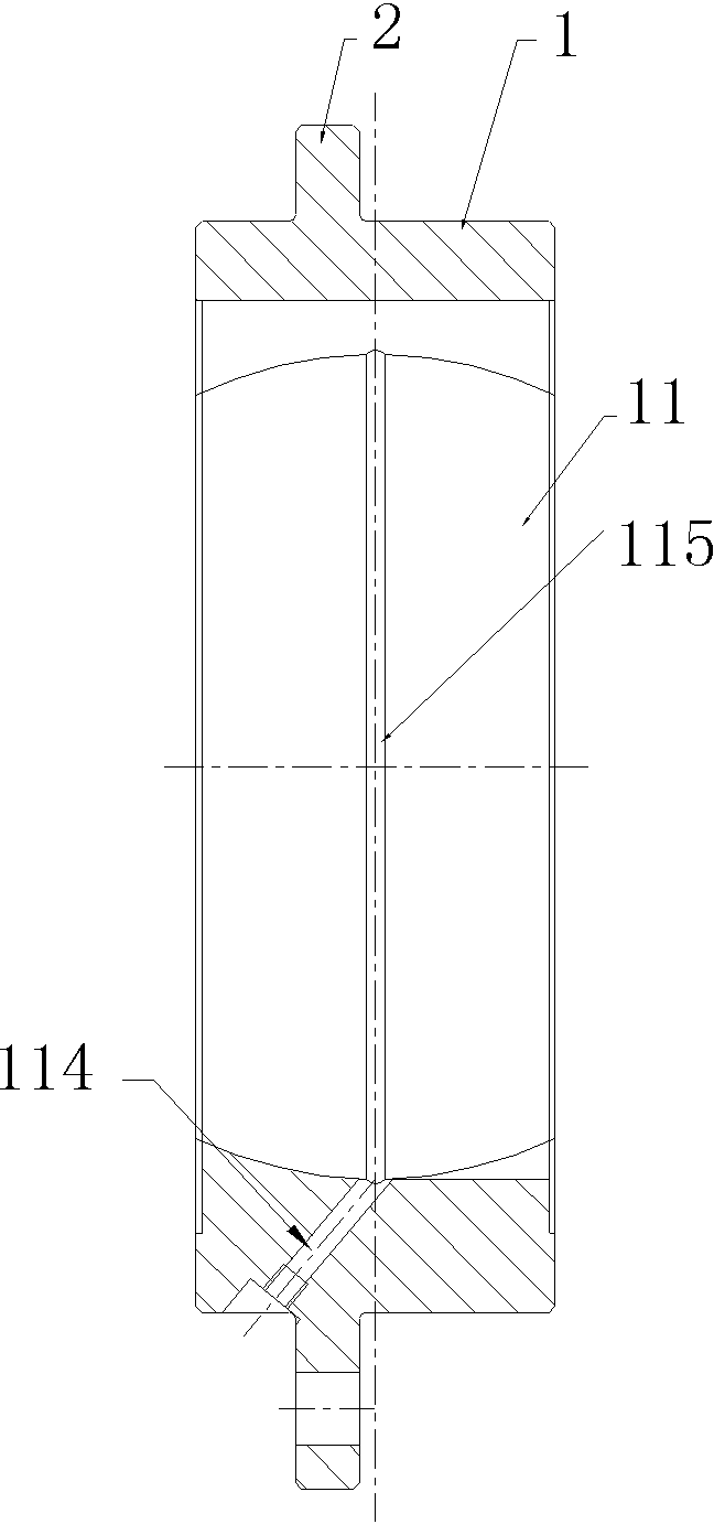
[0018] Embodiment 1 of the spherical hinge seat of the spherical hinge coupling in the present invention is as Figure 1-2 Shown: the ball hinge seat of the ball joint coupling, including the sleeve body 1 and the flange 2 integrally connected to the outer peripheral surface of the sleeve body 1, the inner peripheral surface of the sleeve body 1 is a spherical surface for the ball and the positioning ball The matching inner concave spherical surface 11 is provided with two key grooves 112 extending radially along the sleeve body 1 and used for mating with the head of the force transmission block on the inner concave spherical surface 11. The two key grooves 112 are symmetrically distributed on the sleeve body At both ends of the radial direction of 1, the sleeve body 1 is an integral structure, and the concave spherical surface 11 is provided with an installation groove 113 for inserting the positioning ball along the axial direction of the sleeve body. The installation groove ...


PUM


Abstract

The invention relates to a ball joint coupling, in particular to an assembly method of a ball joint coupling and a ball joint base of the ball joint coupling. The ball joint base comprises a sleeve; the inner peripheral face of the sleeve is a concave spherical face provided with two key grooves; the concave spherical face is further provided with mounting grooves which are used for inserting a positioning ball in the extension direction of the outer end faces of the positioning ball and which penetrate the sleeve in the axial direction; the mounting grooves are in one-to-one correspondence with the key grooves; each mounting groove comprises a groove bottom communicated with the corresponding key groove and sidewalls, the sidewalls arranged on two sides of the groove bottom extend axially along the sleeve and are used for being in contact fit with two outer end faces of the positioning ball so as to insert the same into the mounting grooves, a distance from the groove bottom of the mounting groove to the center of the positioning ball is larger than the radius of the positioning ball and smaller than a distance from the groove bottom of the corresponding key groove to the center of the positioning ball, a distance between the sidewalls of the mounting groove is not smaller than that between the two outer end faces of the positioning ball. By the use of the assembly method of the ball joint coupling and the ball joint base of the ball joint coupling, the problem that the existing ball joint coupling is complex to assemble is solved.

Description

technical field [0001] The invention relates to a ball joint, in particular to an assembly method of the ball joint and a ball joint seat of the ball joint. Background technique [0002] The ball hinge coupling includes a ball hinge seat, a positioning ball, and two force transmission blocks. The torque is transmitted between the positioning ball and the ball joint seat through the force transmission block. The surface includes two parallel and spaced outer end surfaces and a ball-shaped spherical belt surface arranged between the two outer end surfaces. The outer end surface is a plane symmetrical to the equatorial plane of the ball where the spherical belt surface is located. The spherical hinge seat The inner peripheral surface of the ball joint is a concave spherical surface matched with the spherical belt surface of the positioning ball. The ball hinge seat has two installation end surfaces arranged at intervals along the axial direction. The force transmission block in...

Claims


Application Information

Patent Timeline
Patent Type & Authority Applications(China)
IPC IPC(8): F16D3/84F16D3/22F16N1/00
Inventor 杨远航崔德林
Owner 河南蒲瑞精密机械有限公司
Why Eureka
Try Eureka