
Wireless communication system, wireless communication apparatus and wireless communication method

a wireless communication and wireless communication technology, applied in the field of wireless communication systems, wireless communication apparatuses and wireless communication methods using spatial multiplexing, can solve the problems of difficult realization of miniaturization or low cost of apparatuses, and achieve the effects of reducing beamforming dimensions, increasing processing capabilities of channel estimation or computing capabilities, and high transmission rates

Active Publication Date: 2007-11-08
SONY CORP
View PDF8 Cites 68 Cited by
  • Summary
  • Abstract
  • Description
  • Claims
  • Application Information

AI Technical Summary

Benefits of technology

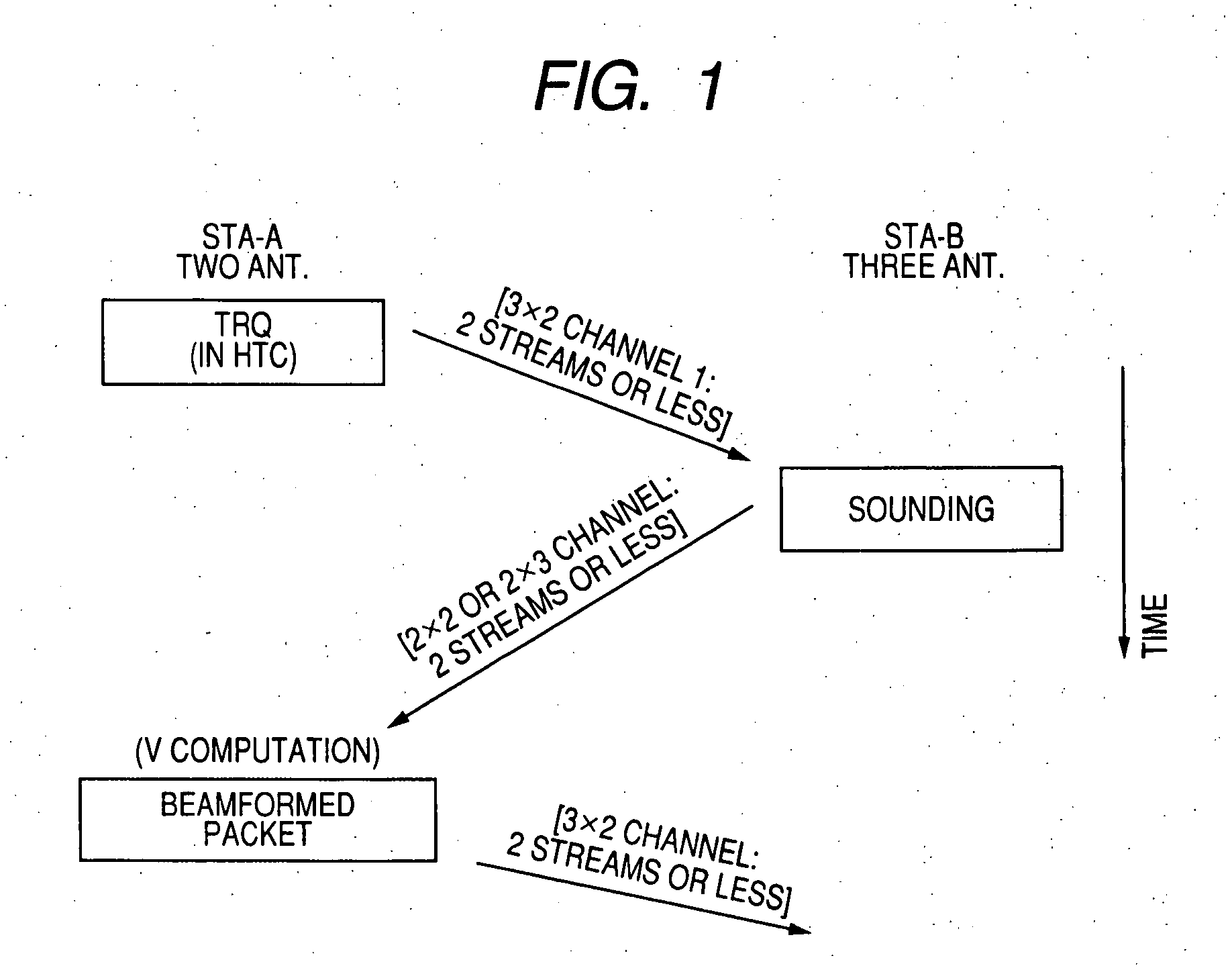
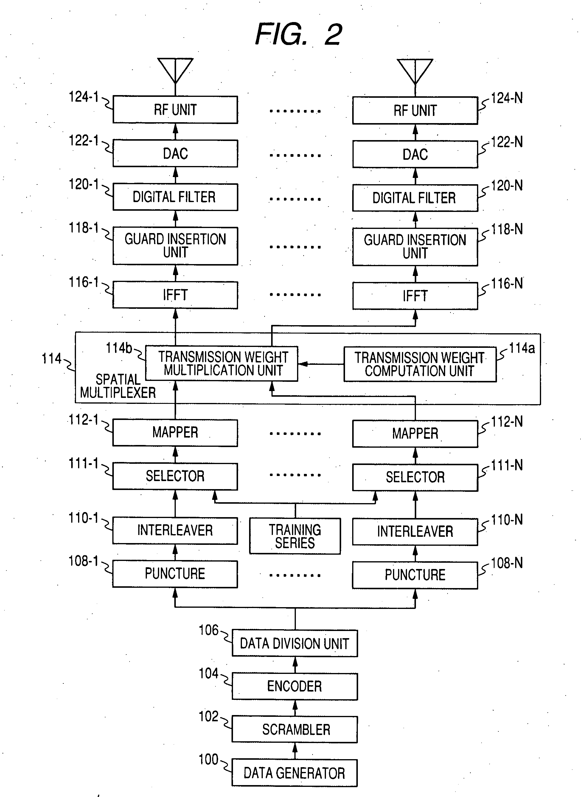
[0039] It is desirable to provide an excellent wireless communication system, wireless communication apparatus and wireless communication method, which are capable of performing communication at a high transmission rate by a beamformed packet by allowing a terminal which operates as a beamformer to divide spatial stream training transmitted from a terminal which operates as a beamformee, to construct an estimation channel matrix from the divided training series, and to suitably obtain a transmission channel matrix for beamforming on the basis of the channel matrix.
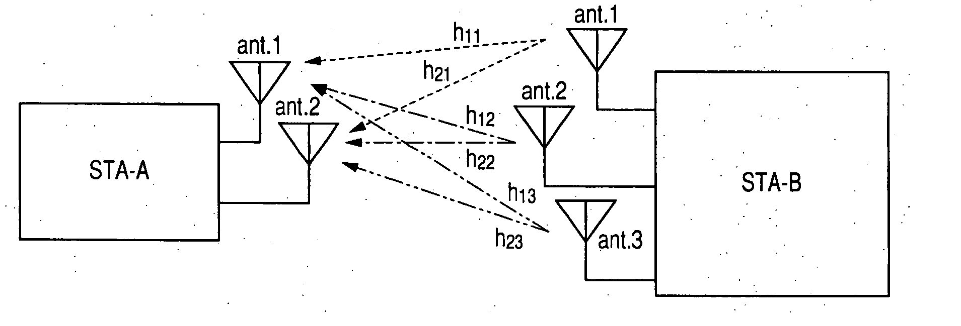
[0040] It is also desirable to provide an excellent wireless communication system, wireless communication apparatus and wireless communication method, which are capable of suitably performing beamforming without deteriorating beamforming characteristics or increasing a processing capability of channel estimation or a computing capability of a matrix for beamforming in the beamformer even when the number of antennas of a terminal which is a beamformer is smaller than that of a beamformee.

Problems solved by technology

However, in a case of N<M, that is, the number of antennas of the beamformee is larger than that of the beamformer, problems may be caused because the beamformer does not include the processing capability which exceeds the number of its own spatial streams.
In this case, since calculation or processing circuit needs to be doubled, miniaturization or low cost of the apparatus is hard to be realized.

Method used


Image

  • Wireless communication system, wireless communication apparatus and wireless communication method
  • Wireless communication system, wireless communication apparatus and wireless communication method
  • Wireless communication system, wireless communication apparatus and wireless communication method

Examples


Embodiment Construction

[0073] Hereinafter, embodiments of the invention will be described in detail with reference to the accompanying drawings.

[0074] A wireless communication system according to the embodiment of the invention performs closed loop type MIMO communication and more particularly, a terminal of a transmitter side performs beamforming by a procedure of performing feedback for a channel matrix, for example, by a procedure of the “implicit feedback” defined in the EWC HT MAC specification.

[0075] In the implicit feedback, a terminal which operates as a beamformer divides spatial stream training transmitted from a terminal which operates as a beamformee, constructs a backward estimation channel matrix from the divided training series, and performs beamforming of a transmission packet using a transmission channel matrix for beamforming obtained on the basis of the channel matrix, thereby performing communication.

[0076] However, a processing capability for performing channel estimation or a proc...


PUM


Abstract

A wireless communication system which performs data transmission from a first terminal including N antennas to a second terminal including M antennas using spatially multiplexed streams (N and M are integers larger than or equal to 2 and N<M) is disclosed. The system includes training request means, training means, channel matrix preparing means, transmission weight matrix computation means, and beamforming means.

Description

CROSS REFERENCES TO RELATED APPLICATIONS [0001] The present invention contains subject matter related to Japanese Patent Application JP 2006-124535 filed in the Japanese Patent Office on Apr. 27, 2006, the entire contents of which being incorporated herein by reference. BACKGROUND [0002] 1. Technical Field [0003] The invention relates to a wireless communication system, a wireless communication apparatus and a wireless communication method using spatial multiplexing, and more particularly, to a wireless communication system, a wireless communication apparatus and a wireless communication method, in which a transmitter and a receiver share channel information to perform closed loop type spatial multiplexing transmission. [0004] In particular, the invention relates to a wireless communication systems a wireless communication apparatus and a wireless communication method, which perform beamforming by obtaining a channel matrix on the basis of training series transmitted from a receiver...

Claims


Application Information

Patent Timeline
IPC IPC(8): H04L1/02H04J99/00H04B7/04H04B7/06H04J11/00H04W16/28
CPCH04B7/0408H04B7/0421H04B7/0634H04B7/0697H04L2025/03796H04L25/03343H04L2025/03414H04L2025/03426H04L2025/0377H04L25/0248
Inventor YAMAURA, TOMOYA
Owner SONY CORP
Learn More