
Image reading apparatus for feature image of live body

a technology for live bodies and feature images, applied in the field of image reading apparatuses, can solve the problems of difficult to receive the influence of the state change on the skin surface, and difficult to obtain excellent fingerprint images under a bad condition. , to achieve the effect of preventing the loss of the thin blood vessel pattern, high precision and high precision

Inactive Publication Date: 2007-11-01
NEC CORP
View PDF15 Cites 94 Cited by
  • Summary
  • Abstract
  • Description
  • Claims
  • Application Information

AI Technical Summary

Benefits of technology

[0024]Therefore, an object of the present invention is to provide an image reading apparatus, which has a small size and a low price and can read a blood vessel pattern of a finger at a high precision by using a 2-dimensional image sensor.
[0025]Another object of the present invention is to provide an image reading apparatus that has a small size and a low price and can read a blood vessel pattern and fingerprint pattern of a finger, at a high precision at the same time by using a 2-dimensional image sensor.
[0035]According to the present invention, it is possible to read the blood vessel pattern of the finger at the high precision by using the 2-dimensional image sensor. This is because, since two kinds of images of a first image of the blood vessel pattern and a second image of the fingerprint pattern are imaged, and a difference between both of the images is obtained to extract a blood vessel image, it is possible to prevent a loss of the thin blood vessel pattern, differently from the conventional technique in which the fingerprint pattern is removed through a smoothing process of the image and in which only the blood vessel pattern is left.
[0036]Also, it is possible to read the fingerprint pattern of the finger together with the blood vessel pattern at a high precision by using the 2-dimensional image sensor. This is because since the detection target and the 2-dimensional image sensor are located in a distance close to each other, the light emitted from the surface of the detection target can be imaged at the excellent contrast.
[0037]Moreover, it is possible to miniaturize the apparatus and make the price cheap. This is because the image forming optical system such as lens is not required.

Problems solved by technology

According to this non-contact method, even in the finger whose skin is stripped due to dermatitis so that it is hard to read the fingerprint because contact of a skin separation portion is difficult in a method where the foregoing contact is assumed, the fingerprint image can be obtained if a portion of a structure inside the skin deriving a skin pattern is reserved, Also, in case of non-contact, it is difficult to receive the influence of the state change on the skin surface, such as a wet or dry state.
In recent years, in conjunction with the advancement of information system, the leakage of person information and the spoofing of a different person in a transaction on a network become problematic.
However, in the conventional fingerprint input apparatus, it is difficult to obtain an excellent fingerprint image under a bad condition such as a wet or dry state of the finger, and skin peeling caused by dermatitis.
Thus, although the fingerprint is not same between all people, it is hardly said to be able to be used for all people.
However, as described in the related art, since the shade of the fingerprint is generated by the contact between the concave and convex sections of the skin and the prism, the image on the skin peeling portion is lost.
Also, the use of the expensive large optical part obstructs the miniaturization and lower price of the apparatus.
However, since the shade of the fingerprint is generated by the contact between the concave convex of the skin and the 2-dimensional image sensor plane, the image on the skin separation portion is lost.
However, any of them has a contact mechanism as the assumption, and the image on the skin peeling portion is lost.
Also, as compared with the optical method, this type of apparatus is weak for the condition change such as the wet or dry-state of the finger.
However, the image on a non-contact portion is lost.
Thus, if the skin is partially stripped because of dermatitis, the fingerprint authentication, namely, the authentication based on the living body feature is difficult.
However, this technique has a problem where in order to miniaturize the apparatus, if the special mechanism for getting a speed of a direction in which the finger is moved is omitted, the image reconfiguration precision of the fingerprint is reduced.
However, in case of the fingerprint detecting apparatus described in the sixth conventional example, a fixing frame for fixing the finger is required and an image forming optical system is also required, which obstructs the operability and miniaturization of the apparatus.
Thus, even if the inner structure of the finger causes a light quantity emitted from the skin surface to be changed, it is scattered on the skin surface, and the event, which is estimated based on a adverse influence caused due to a spread resulting from the distance of the image forming system, resulting in a problem that the fingerprint image of the excellent contrast is not obtained in the portion where the skin is actually stripped.
However, in case of such selection, the influence of the reflection and refraction of the boundary becomes strong which decreases the component reflecting the skin structure.
Thus, this has a problem where it is hard to obtain the contrast of the fingerprint image in which the skin structure originally appearing in the skin separation portion is reflected.
This problem is especially severe in case where a dynamic range is not widely set.
However, the configuration for using the fixing frame for the finger and the image forming optical system as proposed in the sixth conventional example brings about the foregoing problem.
However, in the technique according to the sixth conventional example, a space is required between the fingerprint and an image forming optical system, and for the purpose of the necessity of adjusting the focus, a frame for fixing the finger is required, which disturbs the operability and the miniaturization of the apparatus.
At the same time, when a smoothing process is performed on the image, there is a possibility that not only the finger pattern but also the thin blood vessel image is lost.
Therefore, it is difficult to obtain the blood vessel pattern in a high precision.

Method used


Image

  • Image reading apparatus for feature image of live body
  • Image reading apparatus for feature image of live body
  • Image reading apparatus for feature image of live body

Examples


first embodiment

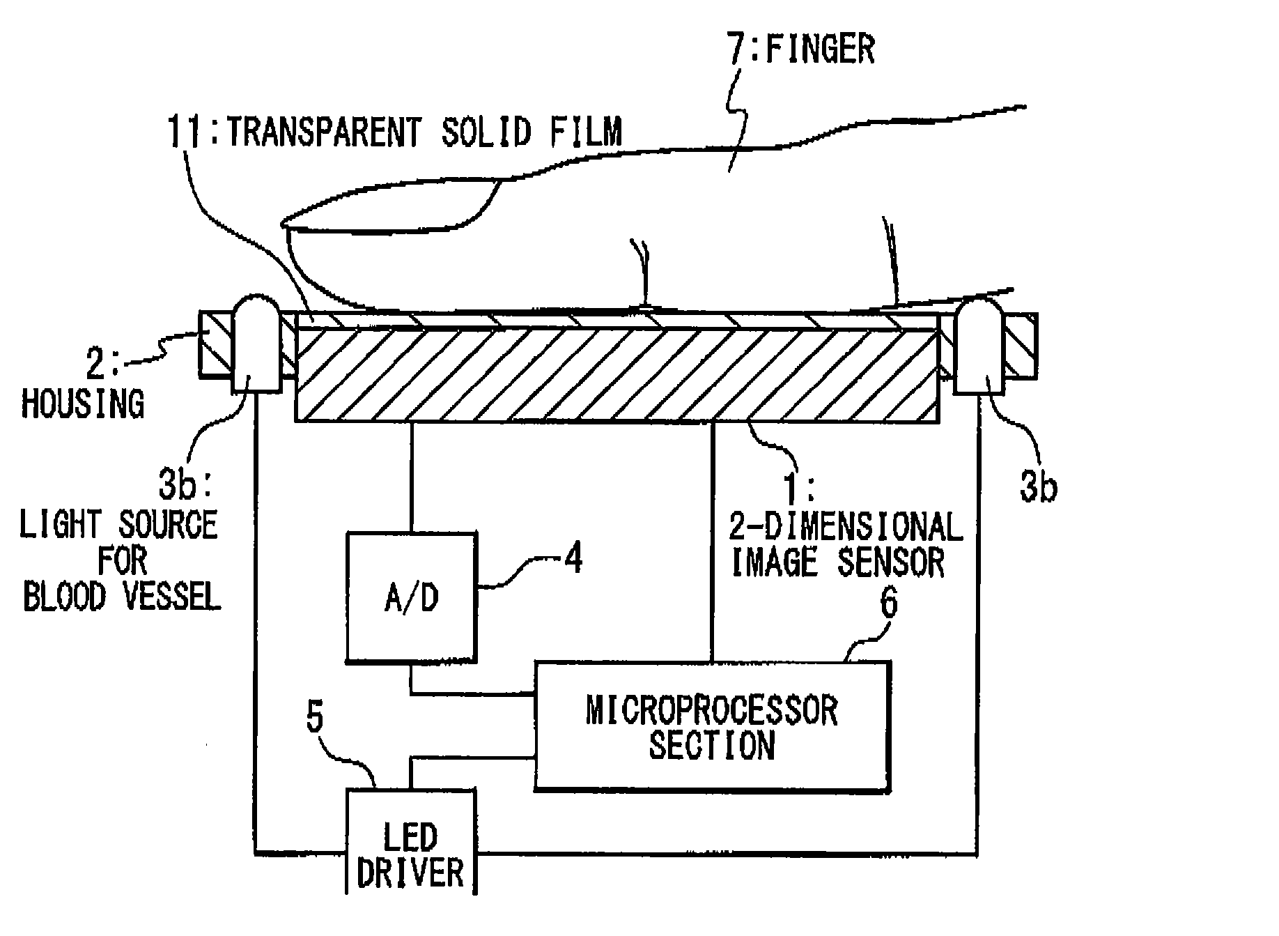
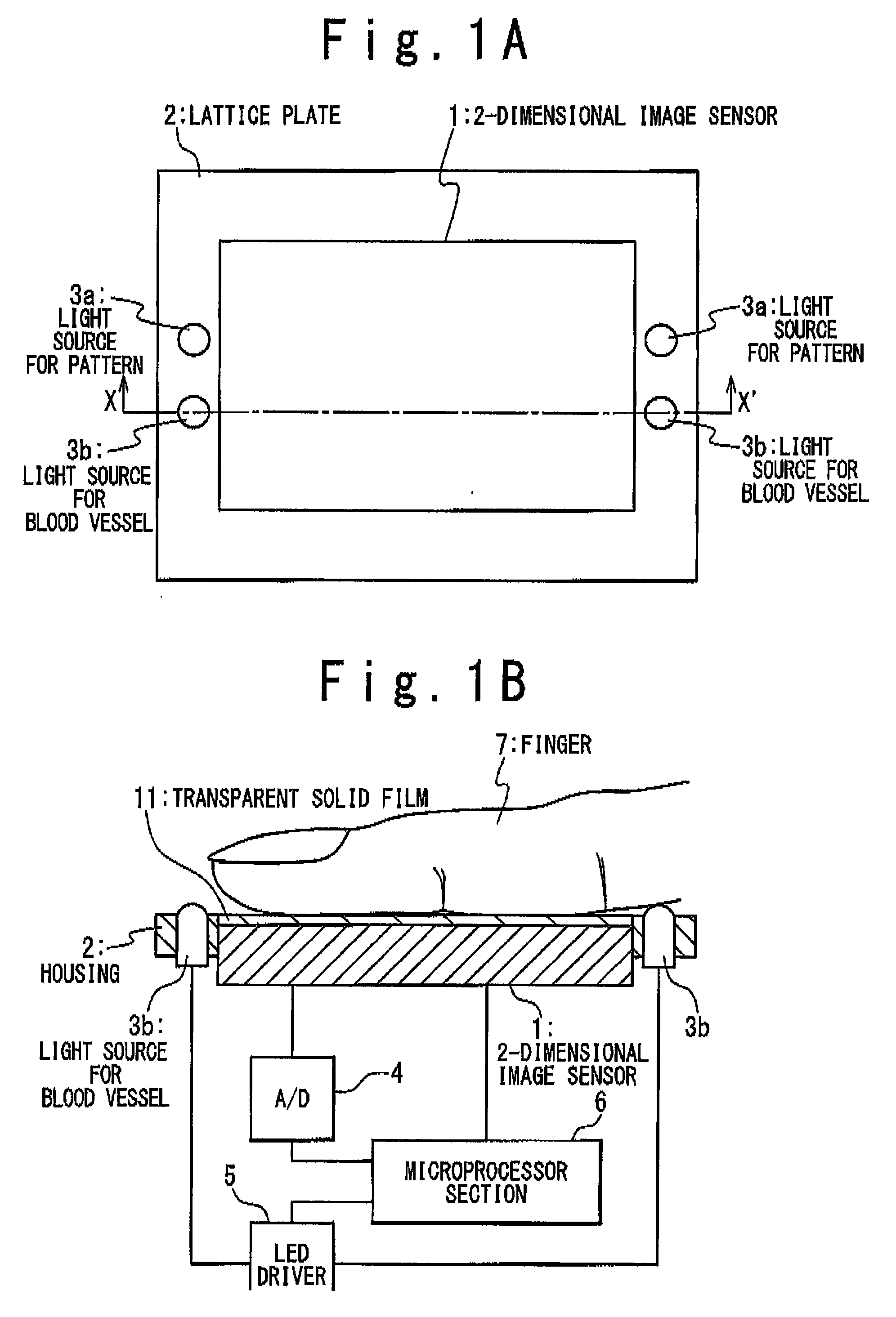
[0062]FIGS. 1A and 1B are a top view and a lateral sectional view showing the image reading apparatus according to the first embodiment of the present invention. With reference to FIGS. 1A and 1B, the image reading apparatus according to this embodiment contains: a 2-dimensional image sensor 1 in which a plurality of light receiving elements (not shown) are arranged in a matrix at a pitch that is narrower than a pitch between a ridge section and a valley section in a fingerprint; a light source 3a for a pattern and a light source 3b for a blood vessel, which are provided for openings in a housing 2 of an electronic equipment to which this 2-dimensional image sensor 1 is attached; an A / D converter 4 for converting an analog output signal of the 2-dimensional image sensor 1 into a digital signal; an LED driver 5 for driving the light sources 3a and 3b; and a microprocessor 6 for performing a control of the imaging timing of the 2-dimensional image sensor 1, a control to turn on / off th...

second embodiment

[0080]With reference FIG. 7, the image reading apparatus according to the second embodiment differs from the first embodiment shown in FIG. 1 in which the light for a fingerprint pattern and a blood vessel pattern is emitted from the side of the finger 7. In the second embodiment, the light source 3a for the fingerprint pattern and the light source 3b for the blood vessel pattern are arranged at the positions opposite to the 2-dimensional image sensor 1 to put the finger 7 serving as the detection sample between the 2-dimensional image sensor 1 and the light sources 3a and 3b. The other components are same as those of the first embodiment.

[0081]As the configuration in which the light sources 3a and 3b are supported above the finger 7, the configuration may be considered in which a cavity having a size to a degree that the finger 7 can be inserted is provided in the housing, the 2-dimensional image sensor 1 is placed on the bottom of the cavity, and the light sources 3a and 3b are at...

third embodiment

[0084]With reference FIG. 8, the image reading apparatus according to the third embodiment differs from the first embodiment shown in FIG. 1 in which the light for the blood vessel pattern is emitted from the side of the finger 7. In the third embodiment, the light source 3b for the blood vessel pattern is arranged at a position opposite to the 2-dimensional image sensor 1 to put the finger 7 serving as the detection sample between the light source 3b and the 2-dimensional image sensor 1. Thus, the light for the blood vessel pattern is emitted from the rear of the finger 7. The other components are same as those of the first embodiment.

[0085]The configuration in which the light source 3b is supported above the finger 7 may be similar to that of the second embodiment. In an example of FIG. 7, the number of light emitting elements of the light source 3b for the blood vessel pattern is one. However, the plurality of light emitting elements of the light sources 3b may be provided.

[0086]...


PUM


Abstract

An image reading apparatus includes first and second light sources configured to emit first and second lights into a detection target, respectively, a 2-dimensional image sensor and a processing unit. The 2-dimensional image sensor has light receiving elements arranged in a matrix, and picks up a light emitted from the detection target through the emission of the first light from the first light source to generate a first image indicating a first pattern corresponding to an internal structure of the detection target, and picks up a light emitted from the detection target through the emission of the second light from the second light source to generate a second image indicating a second pattern corresponding to a surface pattern of the detection target. The processing unit drives the first and second light sources while switching the first and second light sources, and performs a predetermined process on the first and second images.

Description

CROSS REFERENCE[0001]This application relates to the U.S. patent application Ser. No. ______ claiming the priority based on Japanese Patent Application No. 2006-124711 by Teruyuki HIGUCHI and titled “IMAGE READING APPARATUS FOR FEATURE IMAGE OF LIVE BODY” and the PCT application No. PCT / JP2005 / 020905 designating U.S.A. The disclosures of these applications are incorporated herein by reference.BACKGROUND OF THE INVENTION[0002]1. Field of the Invention[0003]The present invention relates to an image reading apparatus, and more particularly relates to an apparatus for reading an image indicating features of a living body such as a fingerprint of a finger and another skin pattern, in order to authenticate a person.[0004]2. Description of Related Art[0005]Conventionally, as an image reading apparatus for authenticating a person by using a finger, an apparatus is known for reading a fingerprint that is a pattern of a skin of a fingertip. Various types of reading apparatus that uses an abso...

Claims


Application Information

Patent Timeline
IPC IPC(8): G06K9/00
CPCG06K9/00026G06K2009/00932G06K9/0012G06V40/1335G06V40/1394G06V40/14
Inventor HIGUCHI, TERUYUKI
Owner NEC CORP
Learn More