
Expandable stent with wrinkle-free elastomeric cover

Active Publication Date: 2007-10-25
WL GORE & ASSOC INC
View PDF26 Cites 51 Cited by
  • Summary
  • Abstract
  • Description
  • Claims
  • Application Information

AI Technical Summary

Benefits of technology

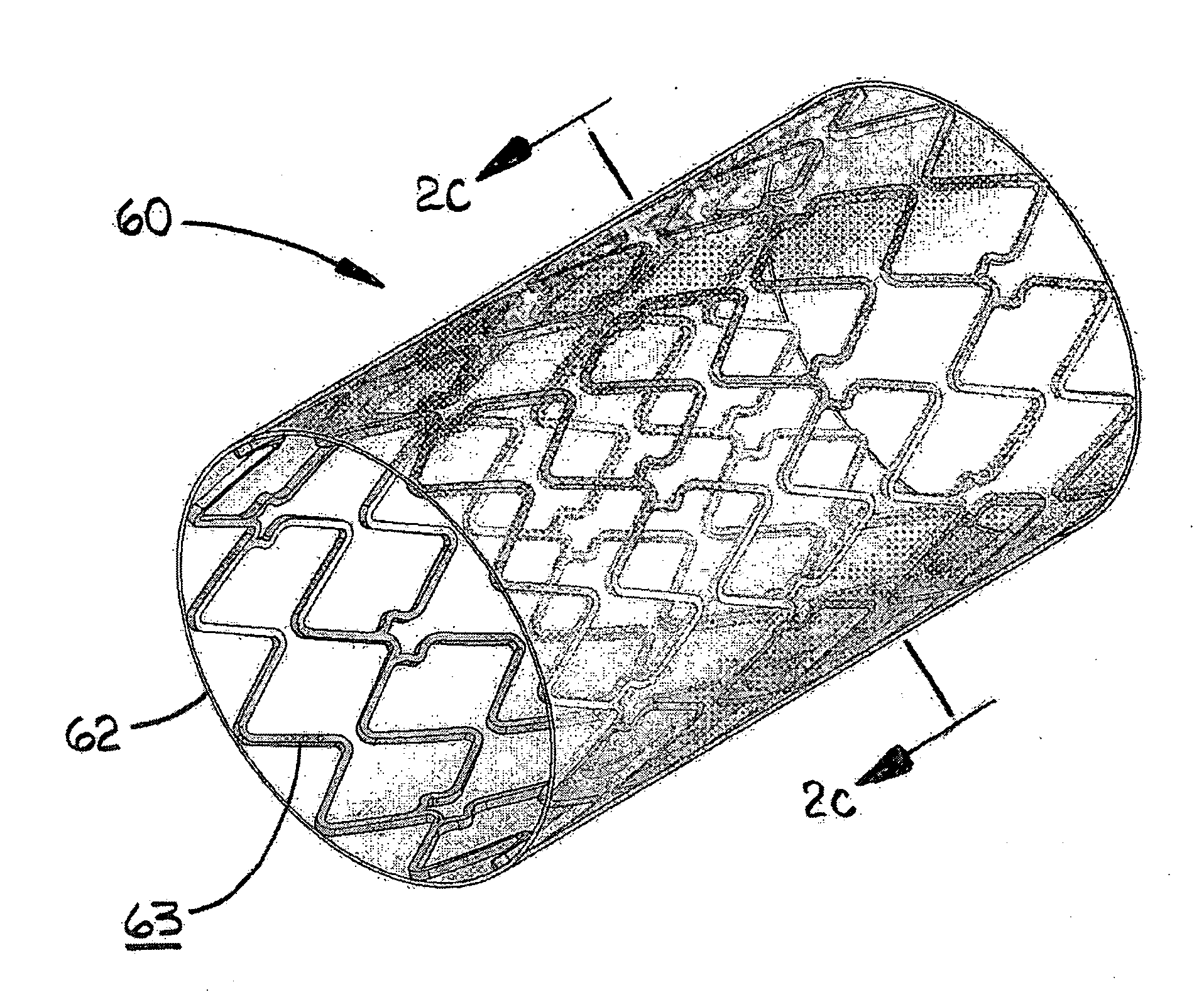
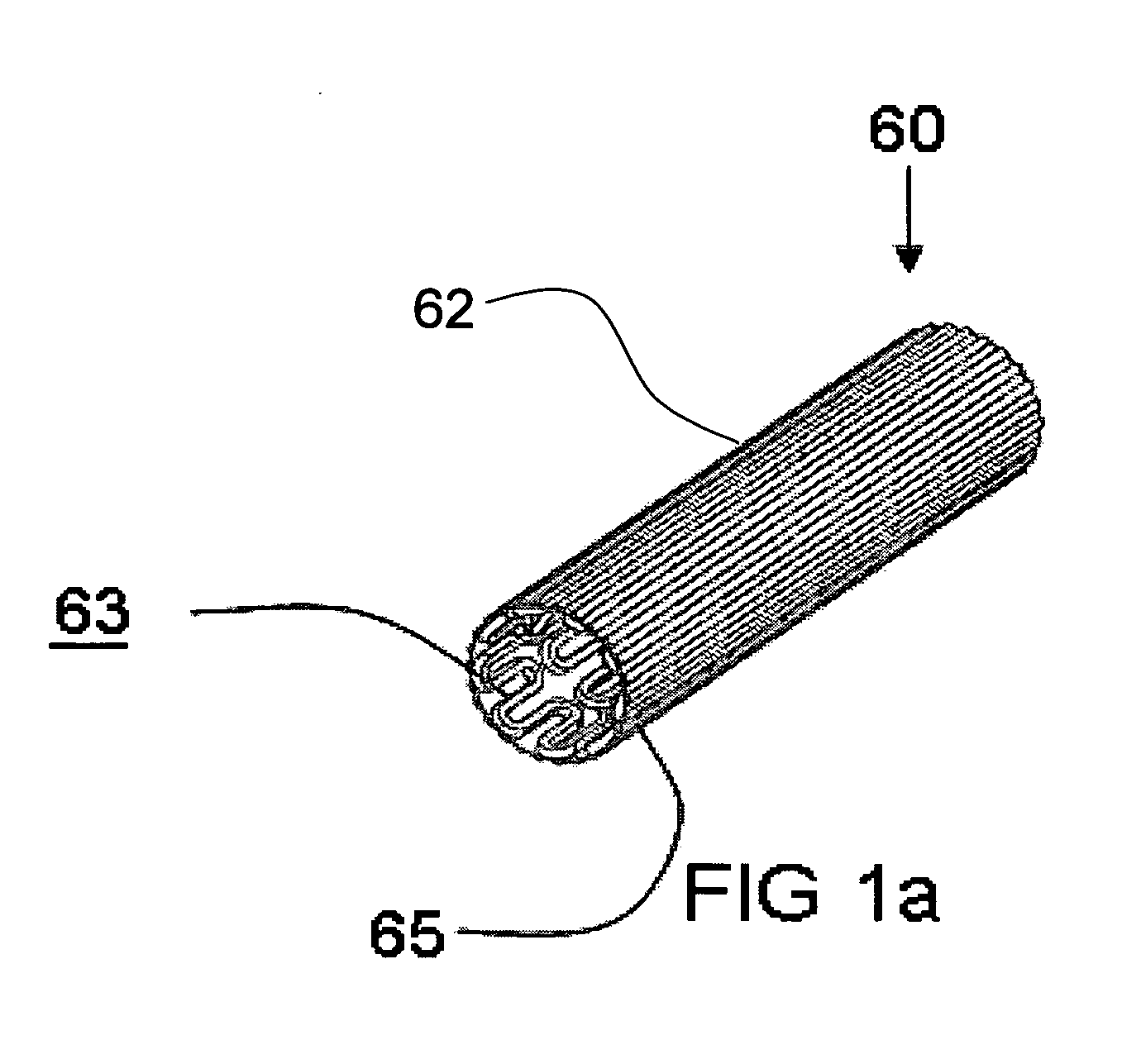
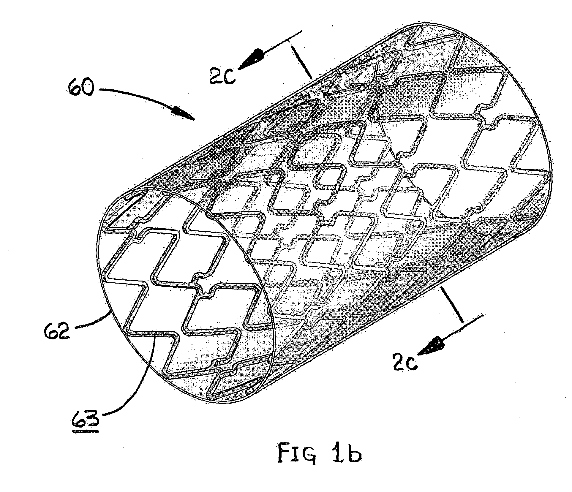
[0022] The present invention is an improved expandable implantable stent-graft device that provides a smooth flow surface over a range of operative expanded diameters. This is accomplished by applying a unique cover material to the stent through a unique technique that allows the cover to become wrinkle-free prior to reaching fully deployed diameter. The unique cover material then allows the device to continue to expand to the fully deployed diameter while maintaining a smooth and coherent flow surface throughout this additional expansion.

Problems solved by technology

However, when the device is unconstrained from the compacted diameter it will self-expand up to the fully deployed diameter with the graft being substantially wrinkle-free over diameters ranging from 50% to 100% of the fully deployed diameter.

Method used


Image

  • Expandable stent with wrinkle-free elastomeric cover
  • Expandable stent with wrinkle-free elastomeric cover
  • Expandable stent with wrinkle-free elastomeric cover

Examples


##ventive example 1

INVENTIVE EXAMPLE 1

[0058] A tubular, self-expanding nitinol stent constructed using the pattern as described in FIG. 4 of U.S. Pat. No. 6,709,453 was obtained. The stent had an outer diameter of approximately 8 mm and a length of about 30 mm. The stent was processed in the following manner. A liquid solution of PMVE-TFE, a liquefied thermoplastic fluoropolymer as described in Example 5 of US Patent Application 2004 / 0024,448 of Chang, et al. was also obtained. PMVE-TFE is an elastomeric material. A relatively dilute solution, 3% by weight, of the polymer was utilized. The stent was dipped into the elastomer solution. The dipped, now covered, stent was removed from the solution, examined to ensure that the elastomer bridged all of the stent openings, and allowed to dry for four hours.

[0059] The elastomer covered stent-graft, a polymer diluting solution FC-77 (3M Fluroinert, 3M Specialty chemicals Division, St Paul, Minn.), tweezers, and a crimping device (such at taught in US 2002 / 01...

##ventive example 3

INVENTIVE EXAMPLE 3

[0064] A tubular, self-expanding stent-graft was made in accordance with the teachings of Example 1 except for the following differences. In this case, a different inventive step was applied to create the wrinkle-free cover. Silicone material (MED-1137 Silicone Adhesive, NuSil Silicone Technology, Carpinteria, Calif.) was used to create the elastomeric covering. A liquid elastomer solution of silicone and heptane was also obtained. A relatively dilute solution, 1% by weight, of the elastomer was created. The stent, elastomer solution, tweezers, and a crimping device were chilled together inside a conventional freezer compartment set to −15° C.

[0065] The chilled crimping device was used to uniformly reduce the diameter of the stent along its entire length. The outer diameter of the stent was reduced to about 4 mm. The following procedure was performed inside the freezer compartment using the chilled tweezers. The stent was dipped into the chilled elastomer solutio...


PUM


Abstract

An improved stent-graft device is provided that delivers a smooth flow surface over a range of operative expanded diameters by applying a unique cover material to the stent through a technique that allows the cover to become wrinkle-free prior to reaching fully deployed diameter. The unique cover material then allows the device to continue to expand to a fully deployed diameter while maintaining a smooth and coherent flow surface throughout this additional expansion. Employed with a self-expanding device, when the device is unconstrained from a compacted diameter it will self-expand up to a fully deployed diameter with the graft being substantially wrinkle-free over diameters ranging from about 30-50% to 100% of the fully deployed diameter. Preferably, the graft component comprises an elastomeric material, such as silicone, polyurethane, or a copolymer of PAVE-TFE.

Description

FIELD OF THE INVENTION [0001] The present invention relates to covered stents for use in various medical procedures. BACKGROUND OF THE INVENTION [0002] The following terms used herein are defined as follows: [0003] The term “stent” means a frame structure containing openings through its wall, typically cylindrical in shape, intended for implantation into the body. A stent may be self-expanding and / or expanded using applied forces. [0004] As used herein, the terms “covered stent” and “stent-graft” are used interchangeably to mean a stent with a cover on at least a portion of its length. The cover may be porous or non-porous and permeable or non-permeable. Active or inactive agents or fillers can be attached to or incorporated into the cover. [0005] Referring to FIG. 4, as used in this application, the term “wrinkle”65 means a fold in a stent cover 62 that has a larger peak to valley height 64 than a thickness 66 of an adjacent stent strut 68. Wrinkles can extend through the stent ope...

Claims


Application Information

Patent Timeline
Patent Type & Authority Applications(United States)
IPC IPC(8): A61F2/06
CPCA61F2/07A61F2/91A61F2/915A61F2002/072A61F2220/005A61F2002/91525A61F2002/91541A61F2002/075A61F2002/91508
Inventor CULLY, EDWARD H.VONESH, MICHAEL J.
Owner WL GORE & ASSOC INC
Learn More