Welding method for heat radiating fin of heat exchanger and equipment thereof

A heat dissipation fin and heat exchanger technology, applied in welding equipment, arc welding equipment, heat exchange equipment, etc., can solve the problems of loose fins, loss of heat conduction and heat exchange function, poor heat conduction and heat dissipation, etc., and improve heat conduction and heat exchange. Thermal performance, welding effect is good, and the effect of prolonging service life

Inactive Publication Date: 2004-11-10
温振武
View PDF0 Cites 16 Cited by
  • Summary
  • Abstract
  • Description
  • Claims
  • Application Information

AI Technical Summary

Problems solved by technology

But it has the following disadvantages: 1. Only fins with a thickness of 03-05 mm can be wound. Because the fins are very thin, the heat conduction and heat dissipation are not good.
2. The contact connection structure between fins and tubes formed by winding makes the heat conduction effect not ideal
3. After the heat exchanger is used for a period of time, the fins become loose due to heat extension and lose the heat conduction and heat exchange function
4. The wrinkles produced by the fins affect the heat transfer effect

Method used


Image

  • Welding method for heat radiating fin of heat exchanger and equipment thereof
  • Welding method for heat radiating fin of heat exchanger and equipment thereof
  • Welding method for heat radiating fin of heat exchanger and equipment thereof

Examples


Embodiment Construction

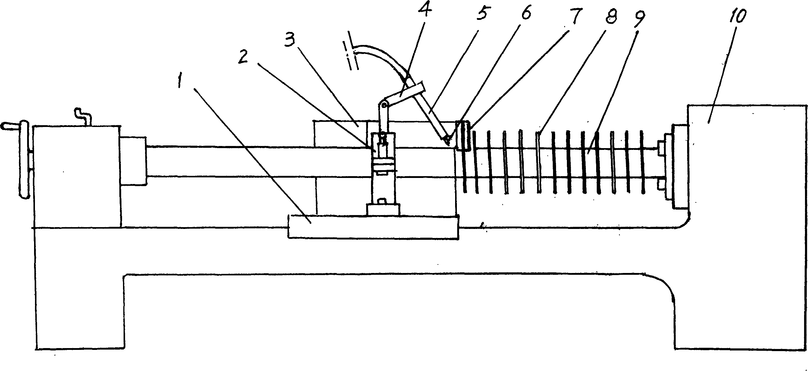
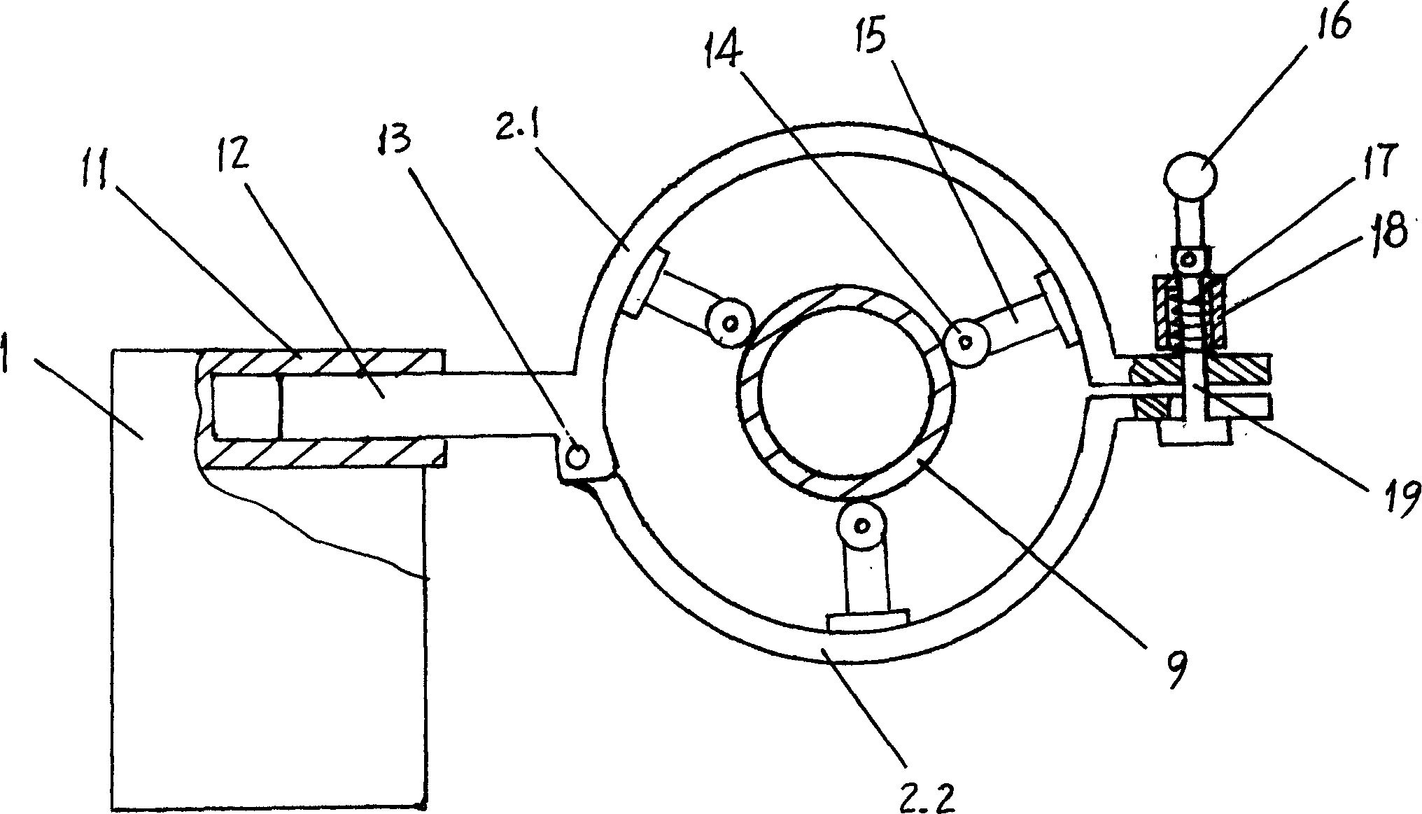
[0015] See Figure 1-3 , heat exchanger cooling fin welding equipment is as follows:

[0016] Set a C618K-1500 type lathe 10 refitted by stepless speed regulation, assemble the follower frame 2 on the tool rest 1, the follower frame 2 has two half-arc parts 2.1, 2.2, and one half-arc part 2.1 is connected with Sliding shaft 12, sliding shaft 12 is slidably inserted in the sliding sleeve 11 on the tool rest 1. One side of the two semi-arc parts 2.1, 2.2 is hinged by a hinge shaft 13 to form an openable and closable circular follower frame, and a locking part is assembled on the side that can be opened and closed. The locking part is provided with a jacket 18, and a spring 17 is housed in the jacket 18 , the connecting screw 19 passes therethrough, and the bottom of the connecting screw 19 penetrates the gap on the connecting edge of the half-arc part 2.2, and its upper end is hinged with the trigger 16 of the arc-shaped end. When the trigger 16 is upright, the spring 17 is co...


PUM


Abstract

The invention is a method of welding cooling fins of a transducer, and its character: the end head of the stainless steel band is welt upright on the steel pine wall, then the steel pipes rotates at uniform speed to apply stretching prestress on the stainless steel band, the steel band is driven by the rotating steel pipe to be wound upright on the steel pipe, at the time of winding, the Wu electrode of an argon-arc welding gun aligns with the horizontal point of tangency between the stainless steel band and the steel pipe and at the time of welding, outputs current to stabilize the arc to weld the roots of the cooling fins. Its advantages: it can continuously weld 1.0 -1.5mm thick, 10-15mm wide steel bands upright on to a stainless steel pipe with a 40-60 mm diameter, and it has good welding effect and enhances heat conducting and transferring performances and prolongs service life of the transducer.

Description

technical field [0001] The invention belongs to a method and equipment for welding cooling fins of a heat exchanger. Background technique [0002] At present, the heat dissipation fin assembly process on oil and gas heat exchangers adopts a simple winding method, that is, a stainless steel strip with a thickness of 03-05 mm and a width of 10-15 mm is vertically wound on a steel pipe through a mold to increase heat transfer The heat exchange area of ​​the device. But it has the following disadvantages: 1. Only fins with a thickness of 03-05 mm can be wound. Because the fins are very thin, the heat conduction and heat dissipation are not good. 2. The contact connection structure between fins and tubes formed by winding makes the heat conduction effect not ideal. 3. After the heat exchanger has been used for a period of time, the fins will loosen due to heat extension and lose the heat conduction and heat exchange function. 4. The wrinkles produced by the fins affect the hea...

Claims


Application Information

Patent Timeline
IPC IPC(8): B23K9/00F28F1/10
Inventor 温振武
Owner 温振武
Why Eureka
Try Eureka