
Single stage integrated boost inverter motor drive circuit

a single-stage, boost technology, applied in the direction of electric variable regulation, process and machine control, instruments, etc., can solve the problems of inability to design the motor to be directly fed by the battery voltage, and inability to meet the requirements of the converter. converter is quite critical, and the copper loss in the wiring and circuit components is unacceptabl

Inactive Publication Date: 2007-10-25
INFINEON TECH AMERICAS CORP
View PDF22 Cites 18 Cited by
  • Summary
  • Abstract
  • Description
  • Claims
  • Application Information

AI Technical Summary

Problems solved by technology

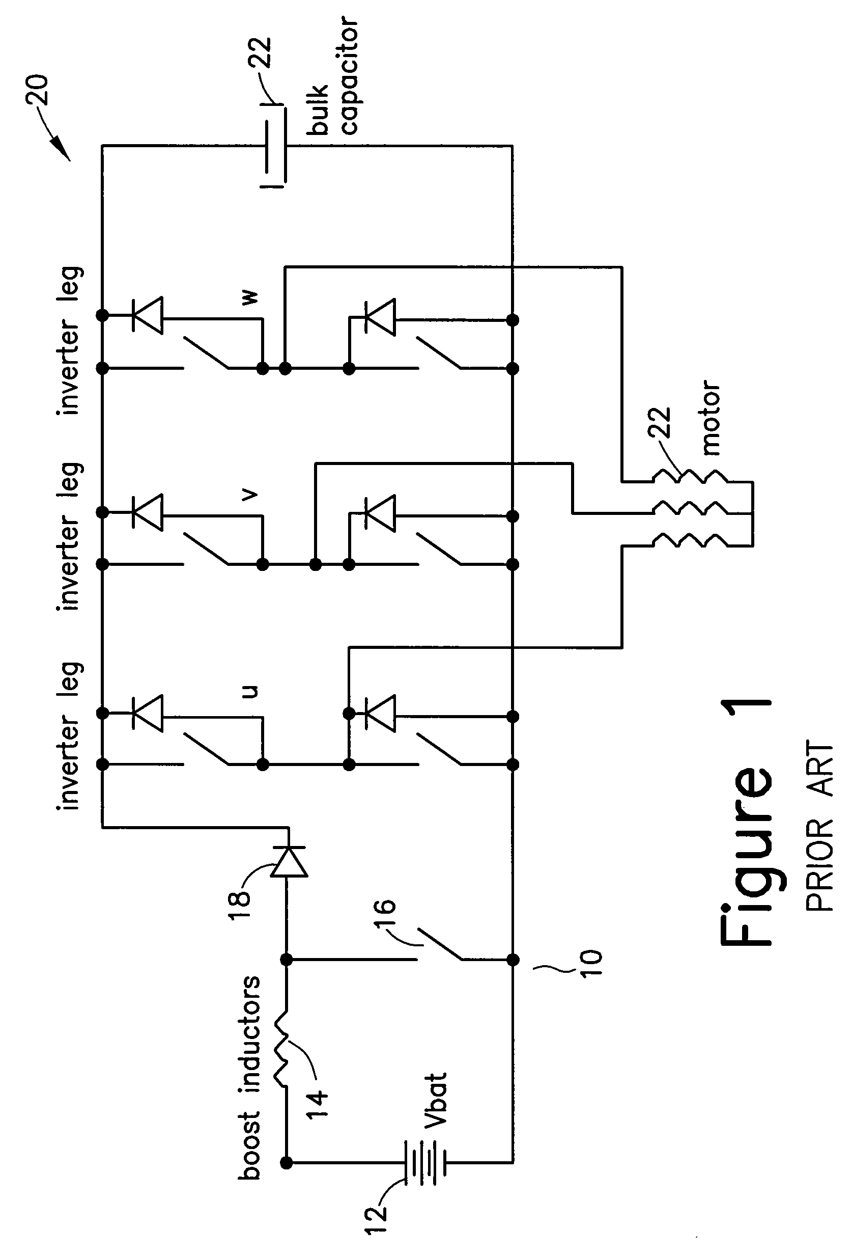
Since the power required by these motors often exceed a few hundreds of Watts, the motors cannot be designed to be directly fed by a battery voltage, i.e., through an inverter.
That is because an otherwise excessive current would be drawn, and copper losses in the wiring and circuit components would be unacceptable.
Such boost converter is quite critical.
This imposes the use of bulky and expensive semiconductors and passive components.

Method used


Image

  • Single stage integrated boost inverter motor drive circuit
  • Single stage integrated boost inverter motor drive circuit
  • Single stage integrated boost inverter motor drive circuit

Examples


Embodiment Construction

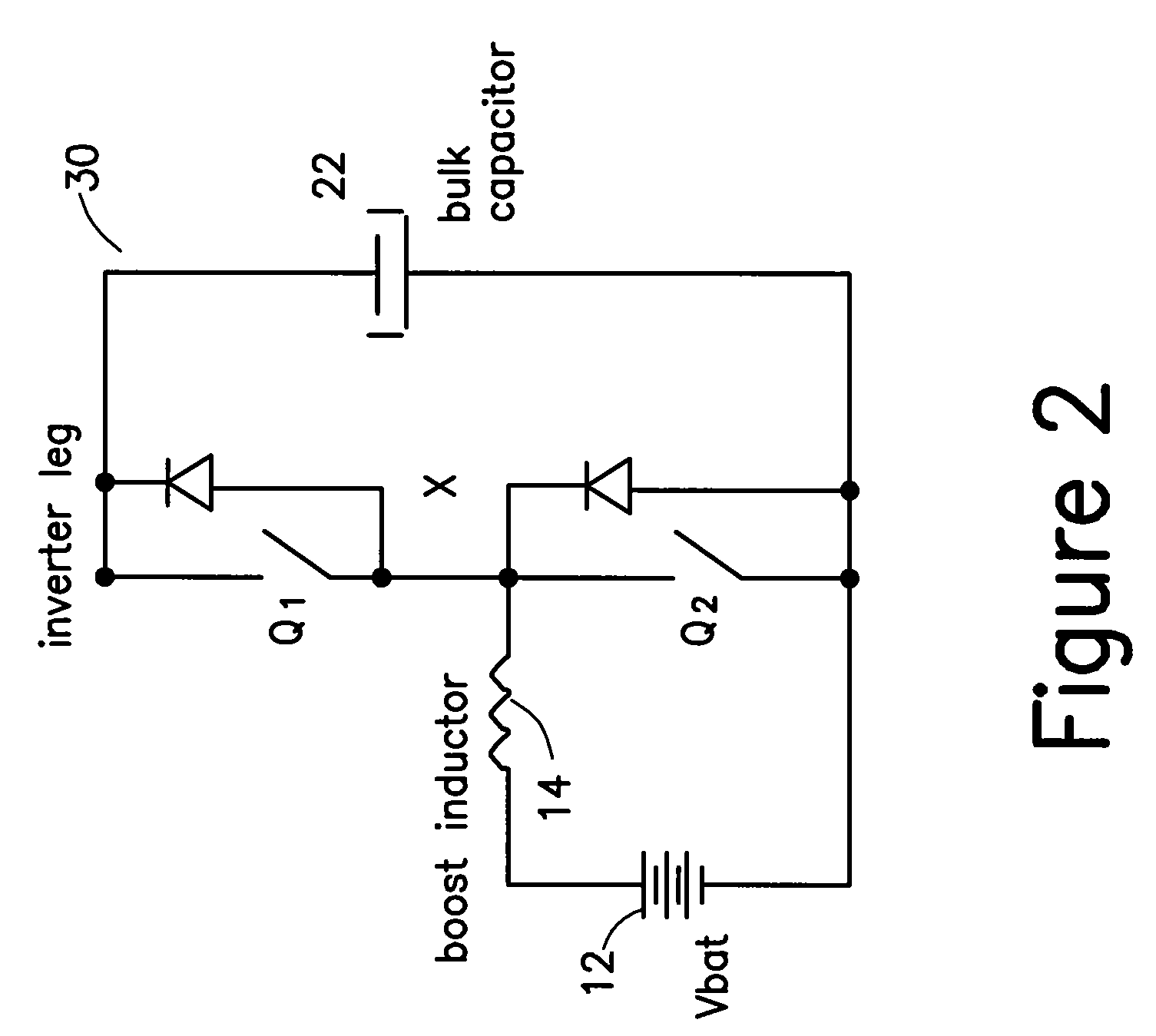
[0019]FIG. 2 illustrates a circuit 30 that integrates a boost converter and an inverter and in a single stage X of the inverter. The present invention proposes to advantageously use the inverter switches Q1 and Q2 as a boost switch in case of the switch Q2 and a diode in case of the switch Q1. The example of the concept is shown for only one leg or stage of the inverter, which may include three or more phases.

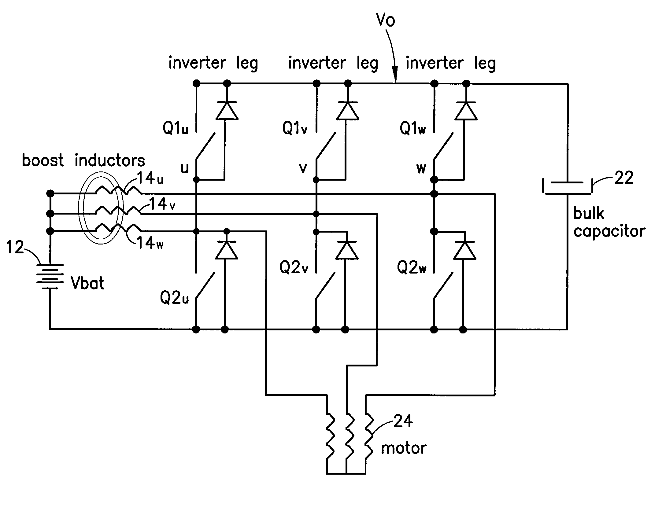
[0020]Using only one leg, i.e., a single inverter stage, as a booster circuit requires oversizing the corresponding switches, and imposes severe limitations to the modulation strategy that is necessary to properly drive the motor. Thus, as illustrated in FIG. 3, it is useful to use all, or three legs / inverter stages U, V, and W, as parallel operated boost converters, in a way that the input current drawn by the battery 12 is shared by three separate circuits, each one comprising one inverter stage U, V, or W, plus an input inductor 14U, 14V, or 14W respectively.

[0021]Each boost...


PUM


Abstract

An integrated boost inverter circuit including at least one inverter stage having series connected high- and low-side switches having a common node. Each switch having an anti-parallel connected diode connected across the switch, which diode can be an external diode or an internal body diode of the switch; at least one inductor connectable in series between a voltage source and the node of the at least one inverter stage; a bulk capacitor connected across the at least one inverter stage; and a load being connectable to the node of the at least one inverter stage, wherein at every switching cycle, when the low-side switch of the at least one inverter stage turns-ON the respective at least one inductor is charged and when the low-side switch turns-OFF, the current in the respective at least one inductor re-circulates through the anti-parallel connected diode of the high-side switch into the bulk capacitor.

Description

CROSS-REFERENCE TO RELATED APPLICATIONS[0001]This application is based on and claims priority to U.S. Provisional Patent Application Ser. No. 60 / 793,094, filed on Apr. 19, 2006 and entitled SINGLE STAGE INTEGRATED BOOST INVERTER MOTOR DRIVE CIRCUIT, the entire contents of which are hereby incorporated by reference herein.BACKGROUND OF THE INVENTION[0002]The present invention relates to variable speed inverter drive circuits and more particularly to inverter drive circuits integrated with a boost converter.[0003]Increasingly, variable speed inverter drive circuits are used in the automotive environment. A number of electrical payloads, which a car battery must feed is increasing with every new car model that is put on the market. It is understood that demand for increased battery power will, in the medium term, oblige most car manufacturers to move from a present 12V battery architecture to higher battery voltages, e.g., 42V, or to a dual battery architecture.[0004]In the meanwhile, ...

Claims


Application Information

Patent Timeline
Patent Type & Authority Applications(United States)
IPC IPC(8): G05F1/00
CPCH02M7/537H02M3/1584H02M7/5387H02M1/0095
Inventor BOCCHIOLA, CESARE
Owner INFINEON TECH AMERICAS CORP
Learn More