
Method and system for reducing pollutant emissions of a power system

Inactive Publication Date: 2007-10-25
CATERPILLAR INC
View PDF11 Cites 6 Cited by
  • Summary
  • Abstract
  • Description
  • Claims
  • Application Information

AI Technical Summary

Benefits of technology

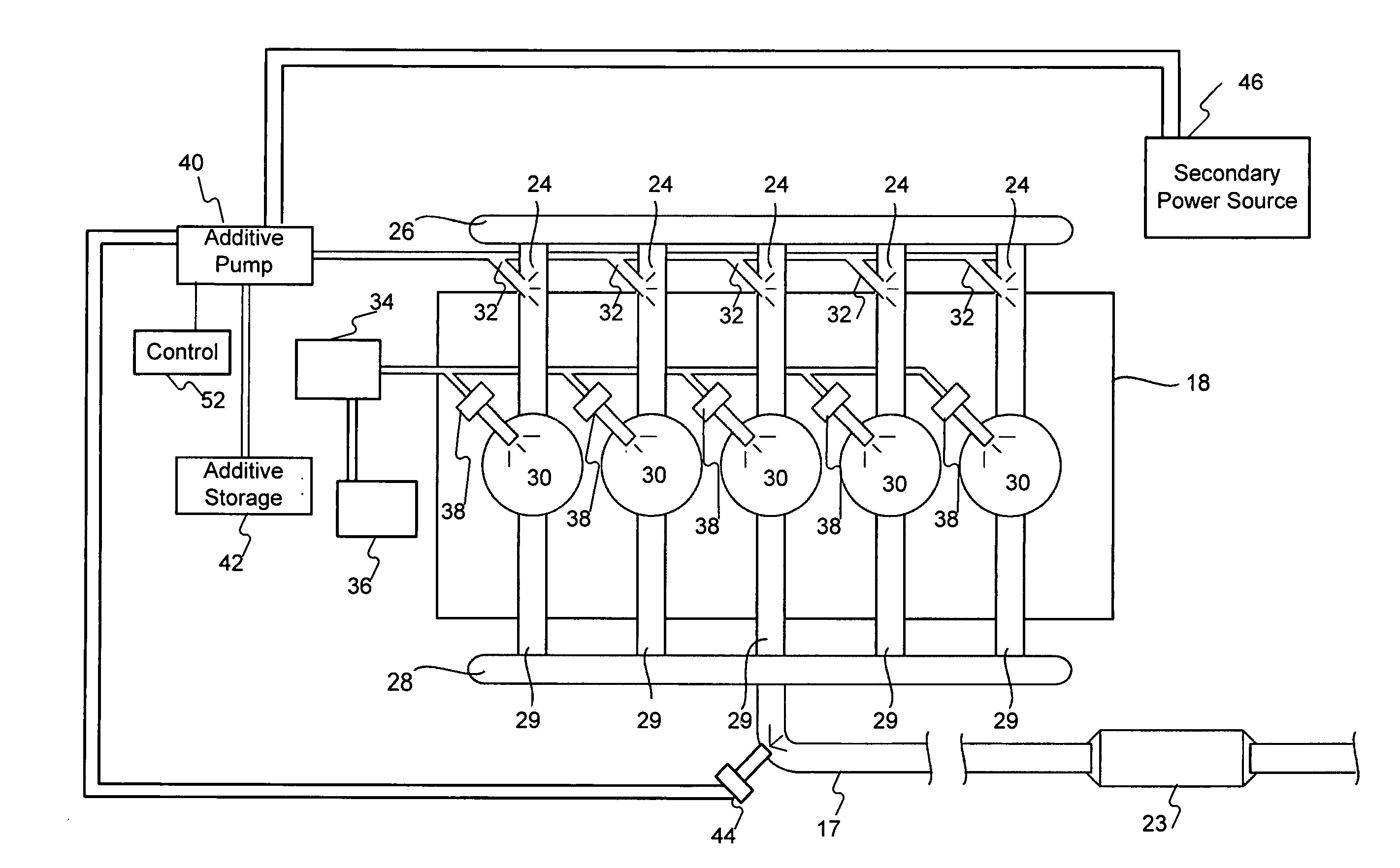
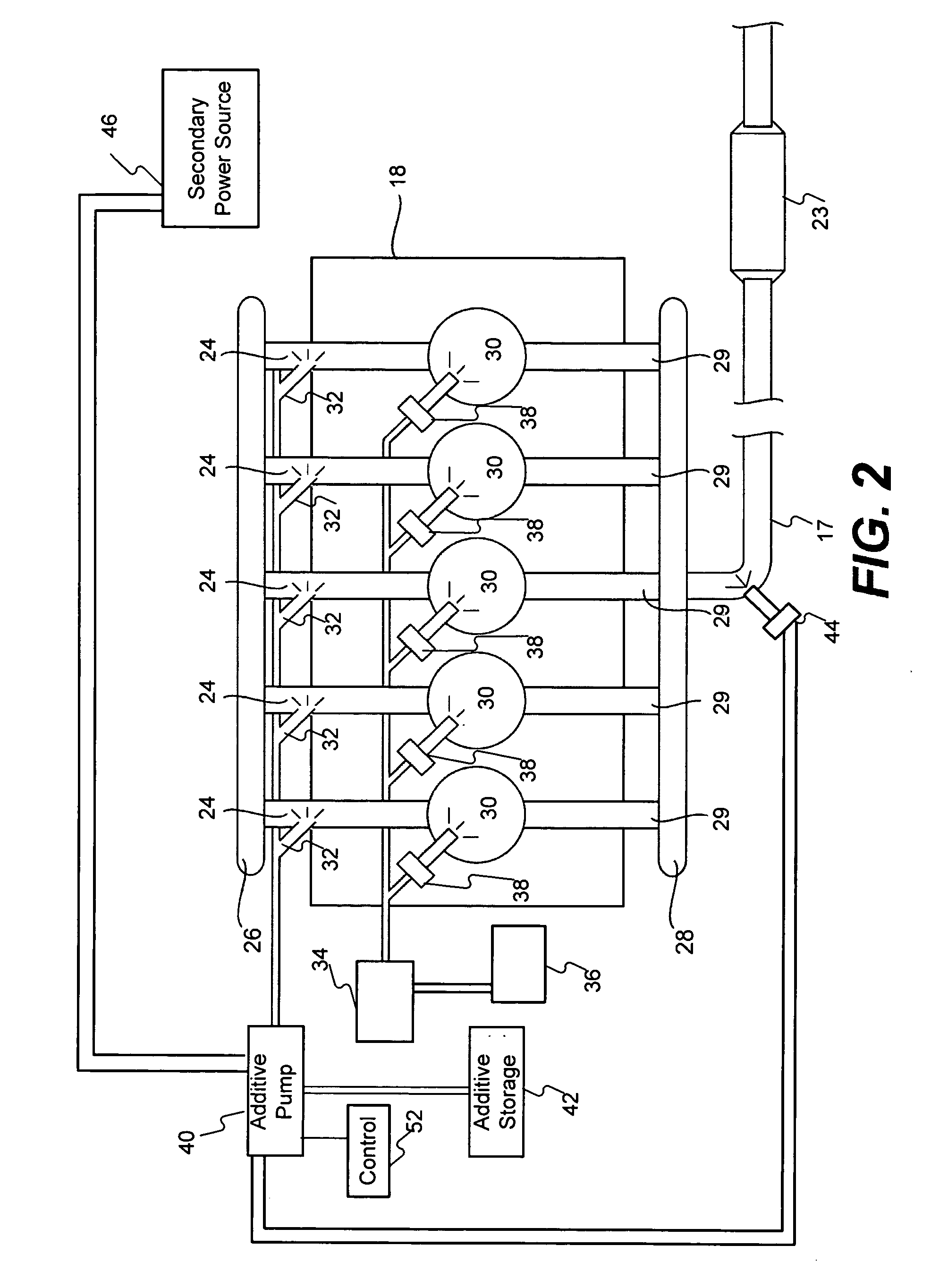
[0013] In one embodiment, the present disclosure is directed to a method for reducing pollutant emissions of a power system. The method may include the steps of providing a first portion of an ethanol additive to a first power source, wherein the first power source includes a combustion chamber, supplying a second portion of the ethanol additive to a second power source, and providing a primary fuel to the combustion chamber. The method may further include the steps of combusting at least a portion of primary fuel and at least some of the first portion of ethanol additive in the combustion chamber, wherein the combustion results in formation of an exhaust-gas stream, providing a third portion of ethanol additive to the exhaust-gas stream, and exposing the exhaust-gas stream to a selective catalytic reduction system catalyst.
[0014] In another embodiment, the present disclosure is directed to a system for reducing emissions. The system may include a first power source, including a combustion chamber and an exhaust system, a second power source configured to receive an ethanol additive, and a controller operatively connected to the first power source and the second power source. The controller may be configured to receive a request for power, determine a first operational state assoc

Problems solved by technology

Government standards associated with combustion engine emissions have increased the burden on manufacturers to reduce the amount of nitrogen oxides (NOx) and other pollutants that may be exhausted from their engines.
However, the sometimes inverse relationship between fuel economy / power and reduced emissions tends to make the task of reducing pollutants while meeting customer needs a daunting one.
These methods may be insufficient to meet standards promulgated by government agencies limiting NOx emissions.
In such a system, NOx in the exhaust-gas stream may react with the injected ethanol in the presence of the catalyst which may result in formation of nitrogen, water, and other byproducts.
However, anhydrous fuel-grade ethanol is a flammable liquid.
Further, injection of the ethanol into the exhaust stream is a waste of energy that could otherwise be extracted from the ethanol.
However, emulsified ethanol is still highly corrosive and lacks the lubricating qualities of petroleum based fuels.
This may result in long-term damage to injection pumps and fuel injectors designed to receive petroleum based fuels exclusively.
Further, emulsions of ethanol within petroleum fuels greater than 15% ethanol by volume, create unstable, reactive emulsions that are impractical for storage or use in an engine.
Further, because the anhydrous fuel-grade ethanol is emulsified in low concentrations and designed for combustion, a majority of the emulsified ethanol is combusted in the combustion chamber, resulting in little if any remaining ethanol to be used as a reductant in the exhaust-gas stream.
While the system of the Kass publication may result in some NOx reduction through ethanol introduced in the exhaust stream, both e-diesel and fuel-grade ethanol can be more difficult to store and manage because of their reactive characteristics.
As a result, added cost may be incurred when using e-diesel and / or fuel-grade ethanol as a reductant injected into an exhaust stream.
In addition, injection of ethanol into an exhaust stream, as taught in the Kass publication, may not result in adequate mixing of the ethanol with the exhaust-gas stream, and, consequently, may result in discharge of unreacted fuel-grade ethanol.
Moreover, injection of ethanol into the exhaust stream may deprive the engine of valuable energy stored within the ethanol, thereby eliminating any benefit to brake specific fuel consumption or use as a fuel for an alternative power source (e.g., a fuel cell).

Method used


Image

  • Method and system for reducing pollutant emissions of a power system
  • Method and system for reducing pollutant emissions of a power system
  • Method and system for reducing pollutant emissions of a power system

Examples


Embodiment Construction

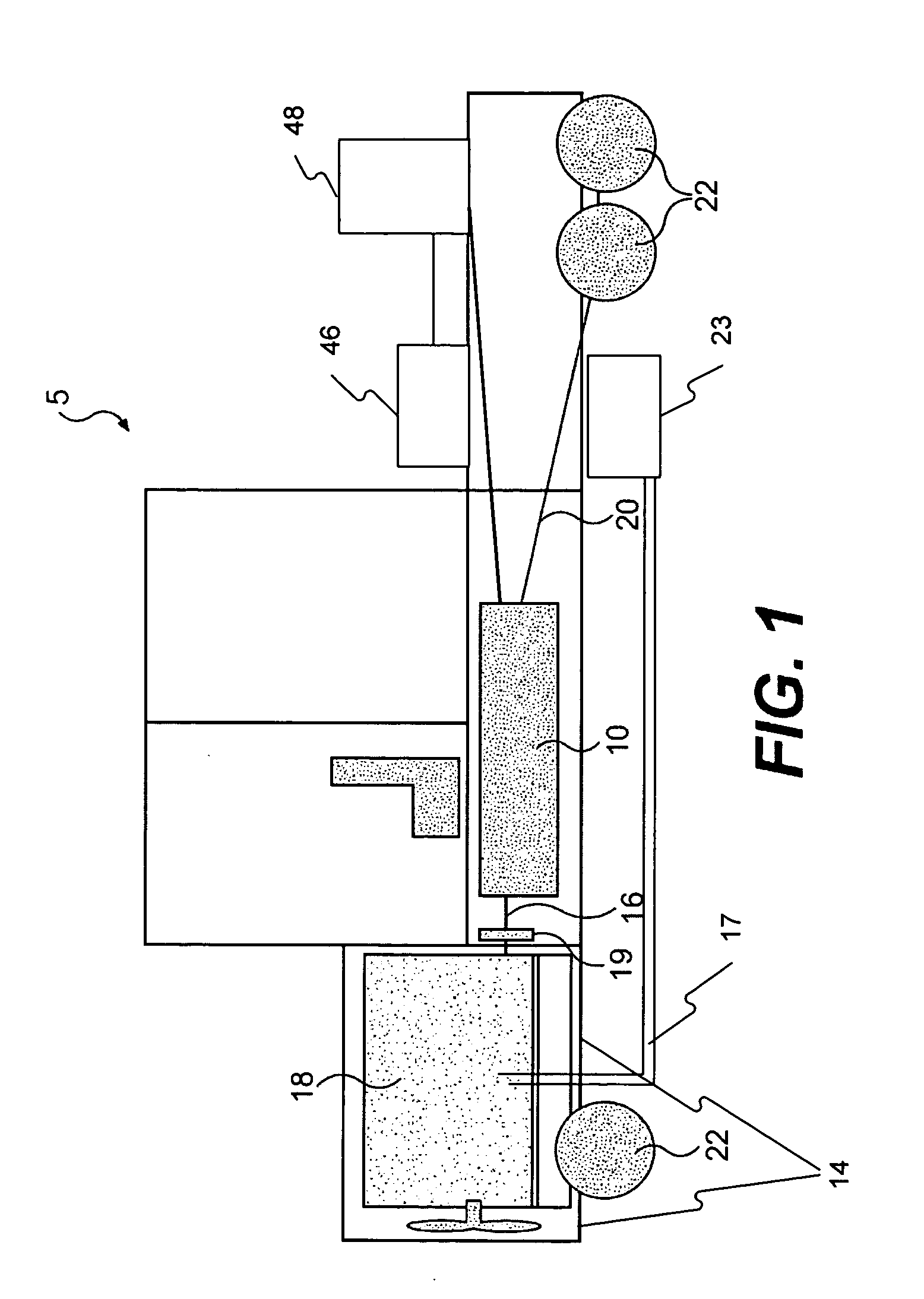
[0019]FIG. 1 provides a pictorial representation of an exemplary machine 5 having multiple systems and components that may cooperate to accomplish a task. Machine 5 may include a system for reducing pollutant emissions. Machine 5 may embody a fixed or mobile machine that performs some type of operation associated with an industry such as mining, construction, farming, transportation, or any other industry known in the art. For example, machine 5 may be an earth moving machine such as an excavator, a dozer, a loader, a backhoe, a motor grader, a dump truck, or any other earth moving machine. Additionally, machine 5 may include on-highway vehicles such as tractors, passenger cars, heavy and light trucks, and other similar vehicles. Machine 5 may include a first power source 18, a second power source 46, auxiliary devices 48, and an input member 16 connecting a transmission assembly 10 to power source 18 via a torque converter 19. Machine 5 may also include a frame 14 and an output mem...


PUM


Abstract

A method for reducing pollutant emissions of a power system may include the steps of providing a first portion of an ethanol additive to a first power source, wherein the first power source includes a combustion chamber. The method may also include supplying a second portion of the ethanol additive to a second power source and providing a primary fuel to the combustion chamber. The method may further include the steps of combusting at least a portion of primary fuel and at least some of the first portion of ethanol additive in the combustion chamber, wherein the combustion results in formation of an exhaust-gas stream, providing a third portion of ethanol additive to the exhaust-gas stream, and exposing the exhaust-gas stream to a selective catalytic reduction system catalyst.

Description

[0001] This application is a continuation-in-part of U.S. patent application Ser. No. 11 / 410,258, entitled “SYSTEM FOR INCREASING EFFICIENCY OF AN SCR CATALYST,” and filed Apr. 25, 2006, which is expressly incorporated herein by reference in its entirety.TECHNICAL FIELD [0002] This disclosure pertains generally to reduction of pollutant emissions and, more particularly, to use of an ethanol additive for reducing both petroleum based fuel use and overall power source emissions. BACKGROUND [0003] Government standards associated with combustion engine emissions have increased the burden on manufacturers to reduce the amount of nitrogen oxides (NOx) and other pollutants that may be exhausted from their engines. Along with this burden is the manufacturer's commitment to their customers to produce powerful yet fuel efficient engines. However, the sometimes inverse relationship between fuel economy / power and reduced emissions tends to make the task of reducing pollutants while meeting cust...

Claims


Application Information

Patent Timeline
IPC IPC(8): F01N3/00F01N3/10
CPCF01N3/2066F02D19/0692F01N2610/00F01N2610/03F02D19/081F02D19/12F02D41/0025F02D41/0275F02M25/00F02M37/0064F02M43/00Y02T10/121Y02T10/36F02D19/0655F02D19/0689F01N2430/04Y02T10/12Y02T10/30
Inventor DRISCOLL, JAMES JOSHUAVACHON, JOHN THOMASJOHNSTON, DARRIN A.
Owner CATERPILLAR INC
Learn More