
Exhaust duct for a fossil fuel powered engine comprising a dilution selective catalytic reduction system

Pending Publication Date: 2019-11-14
NEM ENERGY
View PDF0 Cites 0 Cited by
  • Summary
  • Abstract
  • Description
  • Claims
  • Application Information

AI Technical Summary

Benefits of technology

The invention is about a new exhaust duct for a fossil fuel engine, which helps to reduce emissions of pollutants during operation. There is also a mixing device that can be used with this exhaust duct. Overall, this invention can help to improve the efficiency and reduce harmful emissions from gas turbines.

Problems solved by technology

These gas turbines operate for relatively short time periods and often at part load.
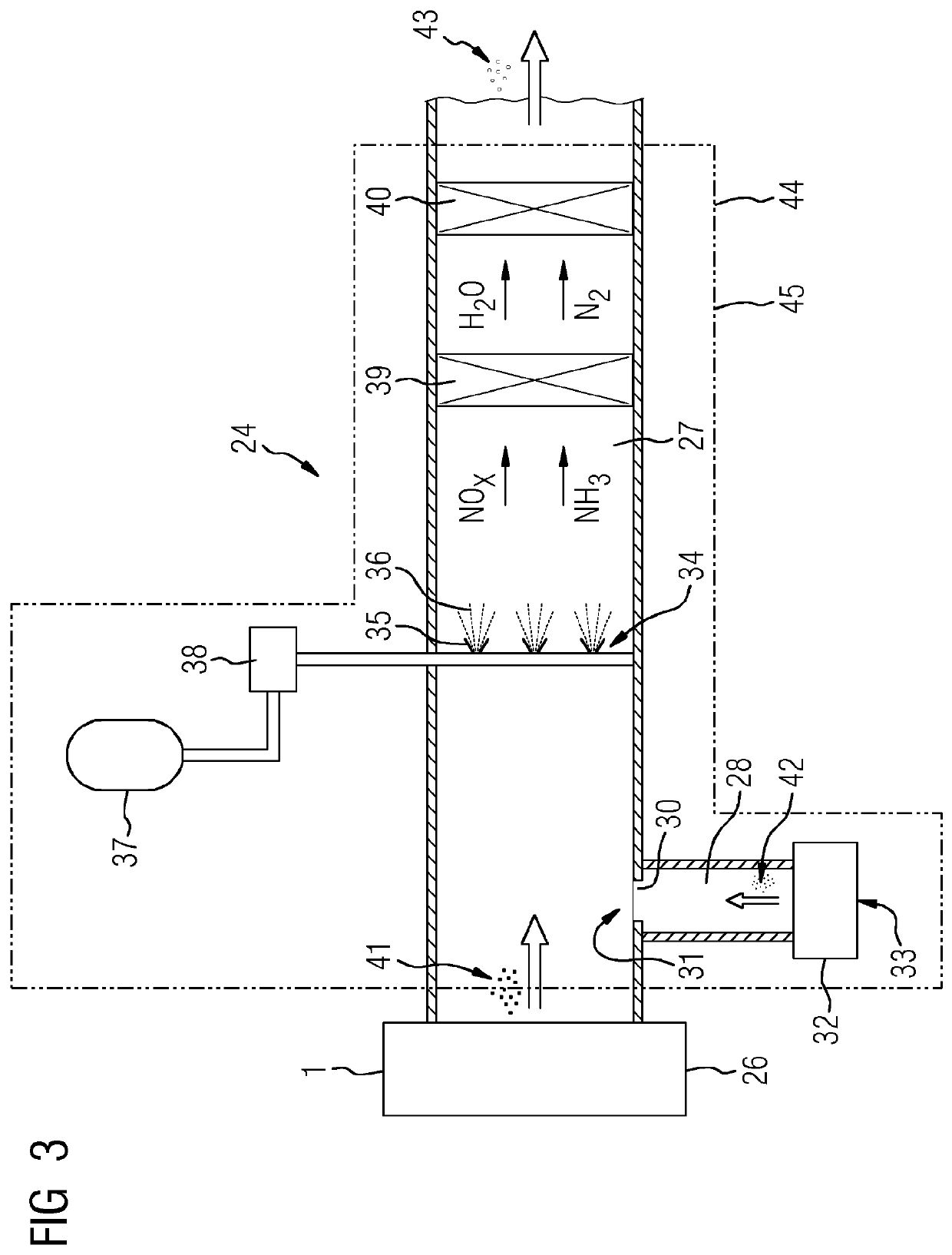
If an exhaust duct of a simple cycle gas turbine is equipped with a dilution-SCR system as suggested, some of the following problems might arise:—Poor mixing of the hot flue gas and the cooling gas,—Different NOx concentration profiles at different gas turbine loads.
This can lead to very non uniform velocity profiles at the catalyzer.
This result in varying residence time throughout the catalyzer and can lead to poor conversion of NOx and reducing agent (unconverted ammonia and / or urea exiting the catalyzer—referred to as NH3 slip).

Method used


Image

  • Exhaust duct for a fossil fuel powered engine comprising a dilution selective catalytic reduction system
  • Exhaust duct for a fossil fuel powered engine comprising a dilution selective catalytic reduction system
  • Exhaust duct for a fossil fuel powered engine comprising a dilution selective catalytic reduction system

Examples


Embodiment Construction

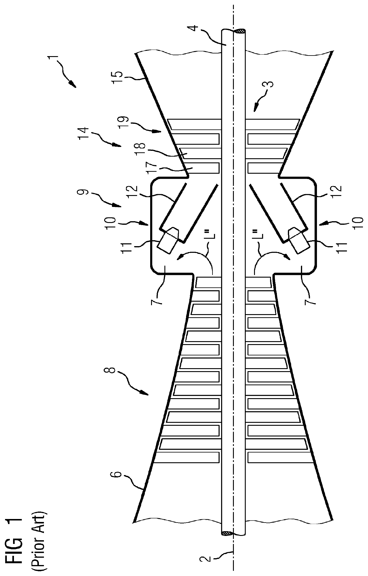
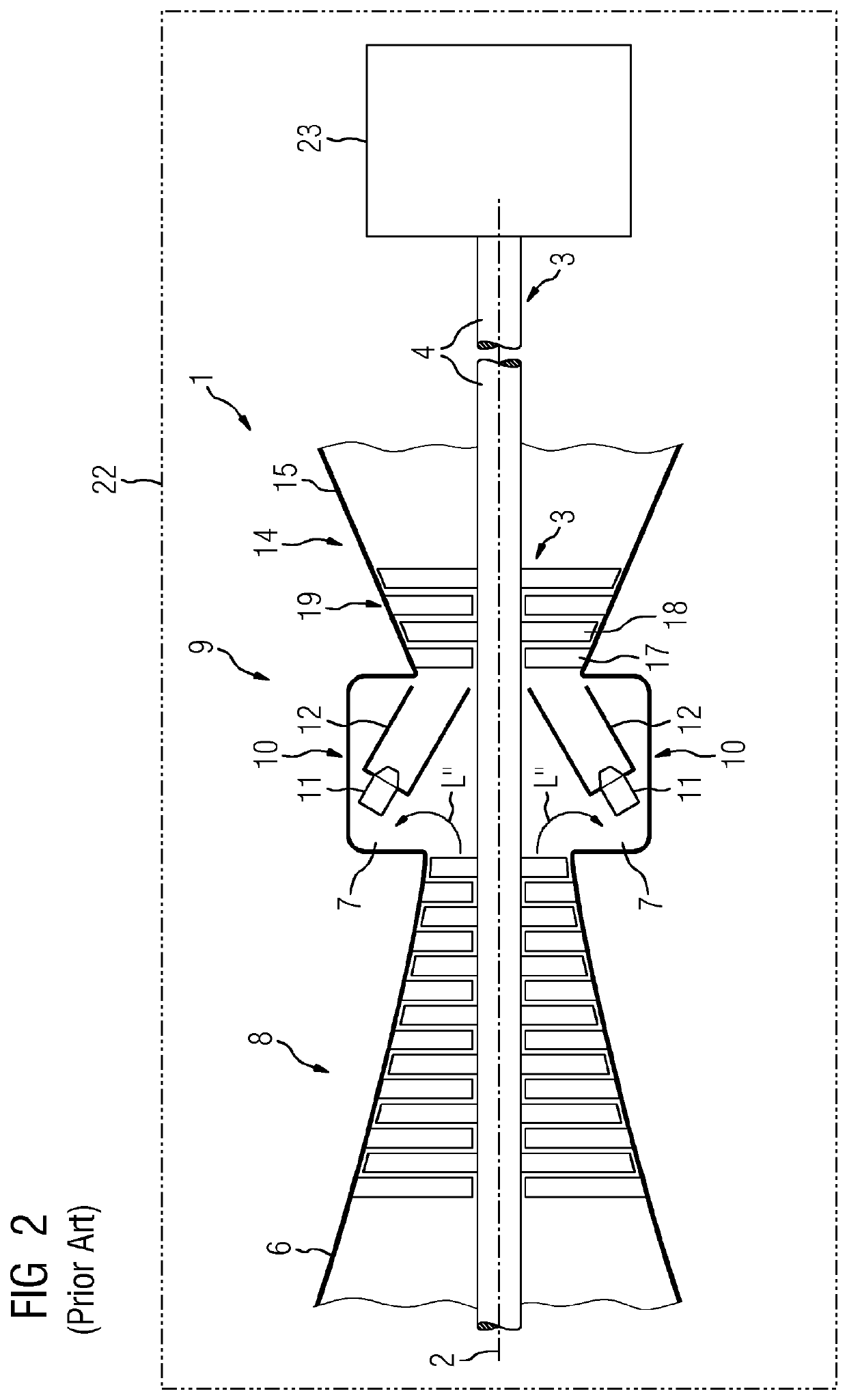
[0040]FIG. 1 shows a sectional view of a gas turbine 1 according to the prior art, in a schematically simplified representation. In its interior, the gas turbine 1 has a rotor 3, which is mounted so as to be rotatable about a rotation axis 2, and which has a shaft 4, which is also referred to as a turbine rotor. Along the rotor 3, in succession, there is an intake housing 6, a compressor 8, a combustion system 9, having one or more combustion chambers 10, which each comprise a burner arrangement having burners 11, a fuel supply system (not represented) for the burners, and a combustion chamber housing 12, and a turbine 14 and an exhaust duct 15. The combustion chamber 10 may be, for example, an annular combustion chamber.

[0041]The combustion system 9 represented in FIG. 1 communicates with a, for example annular, hot-gas channel. There, a plurality of turbine stages connected in succession constituting the turbine 14. Each turbine stage is constituted by blade rings. As viewed in th...


PUM

PropertyMeasurementUnit
Fractionaaaaaaaaaa
Pressure dropaaaaaaaaaa
Areaaaaaaaaaaa

Abstract

An exhaust duct for a fossil fuel powered engine includes an exhaust gas passage, a cooling fluid passage, a mixing device for mixing cooling fluid with the hot exhaust gas and a selective catalytic reduction catalyst for removing nitrogen oxides arranged in the exhaust gas passage. The mixing device has a mixing chamber with a first wall and an opposed second wall, the first and second wall arranged upstream of the selective catalytic reduction catalyst in the exhaust gas passage and extending over the cross-sectional area of the exhaust gas passage, both walls perforated by through holes, wherein through holes of the first wall are connected with through holes of the second wall in pairs by pipes extending through the mixing chamber, the pipes perforated by at least one hole into the mixing chamber and the cooling fluid passage ending into the mixing chamber.

Description

CROSS REFERENCE TO RELATED APPLICATIONS[0001]This application is the US National Stage of International Application No. PCT / EP2018 / 050670 filed Jan. 11, 2018, and claims the benefit thereof. The International Application claims the benefit of European Application No. EP17153522 filed Jan. 27, 2017. All of the applications are incorporated by reference herein in their entirety.FIELD OF INVENTION[0002]The present invention relates to an exhaust duct for a fossil fuel powered engine comprising a dilution selective catalytic reduction system.[0003]The exhaust duct comprising: an exhaust gas passage, a cooling fluid passage, a mixing device for mixing cooling fluid with hot exhaust gas and at least a selective catalytic reduction catalyst (SCR catalyst) arranged in the exhaust gas passage for removing nitrogen oxides (NOx) and at least first means for supplying a reducing agent.[0004]Additional to that, the present invention relates to a mixing device for such an exhaust duct and a power...

Claims


Application Information

Patent Timeline
IPC IPC(8): F01D25/30F02C7/141F02C7/18B01D53/94F01N3/20F01N3/28B01F3/04B01F3/20B01F5/04B01F23/70
CPCF01N2610/02B01F5/0463B01F3/04049B01F5/0493F05D2260/232F01N3/2066B01D53/9431F01N3/2892F01D25/305F05D2220/32F01N2610/11B01F3/2014F02C7/141F02C7/18B01F23/2132B01F23/702B01F25/00B01F25/31331B01F25/31434Y02T10/12
Inventor TOONSSEN, RICHARD
Owner NEM ENERGY
Learn More