Eureka AIR delivers breakthrough ideas for toughest innovation challenges, trusted by R&D personnel around the world.

Dynamic value reporting for wireless automated systems

a wireless automated system and dynamic value technology, applied in the field of remote monitoring of conditions, can solve the problems of large amount of power, large amount of wireless network bandwidth, and large so as to reduce the amount of wireless network traffic, and increase the number of devices communicating over the network

Active Publication Date: 2007-10-18
OLLNOVA TECH LTD
View PDF1 Cites 74 Cited by
  • Summary
  • Abstract
  • Description
  • Claims
  • Application Information

AI Technical Summary

Benefits of technology

"The described embodiments are about a wireless automation system that uses dynamic value reporting to minimize the amount of information reported by sensors. This reduces the amount of wireless traffic in the system and allows for a more robust process control. The system monitors conditions and sends a signal if the condition changes, exceeds a limit, or is outside a range. The controller then sends information about the condition at a variable periodic interval. This information can be transmitted in response to changes in the condition, a control signal, or a stand-by mode. The invention helps to improve the efficiency and reliability of wireless automation systems."

Problems solved by technology

Wireless networks are limited by the amount of available bandwidth over which the devices may communicate.
Systems having many wireless devices may create a noisy environment in which data can be lost, dropped or not communicated with the targeted recipient.
The continuous monitoring of conditions and broadcast of information consumes larges amounts of power, which may shorten a limited-lifetime power source.
The continuous stream of information from and to devices uses a great amount processing power for a controller, and may provide redundant information that may need to be filtered before being processed.

Method used


Image

  • Dynamic value reporting for wireless automated systems
  • Dynamic value reporting for wireless automated systems
  • Dynamic value reporting for wireless automated systems

Examples


Embodiment Construction

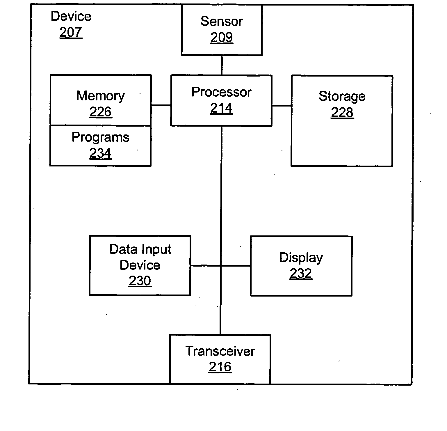
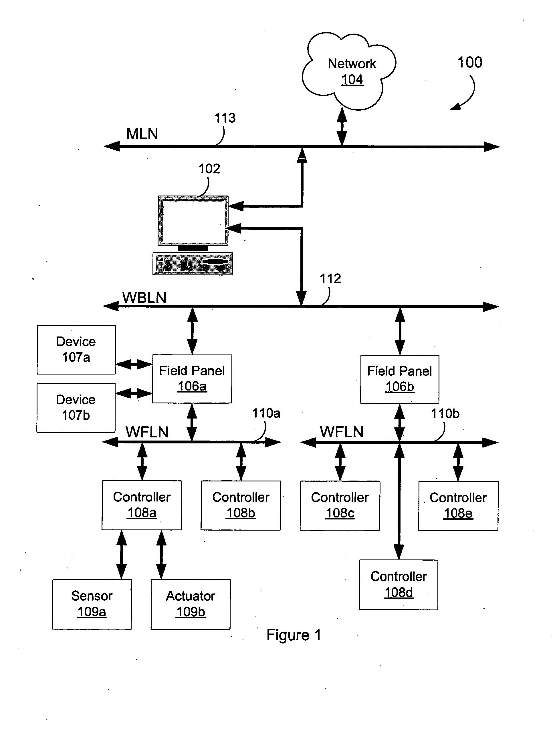
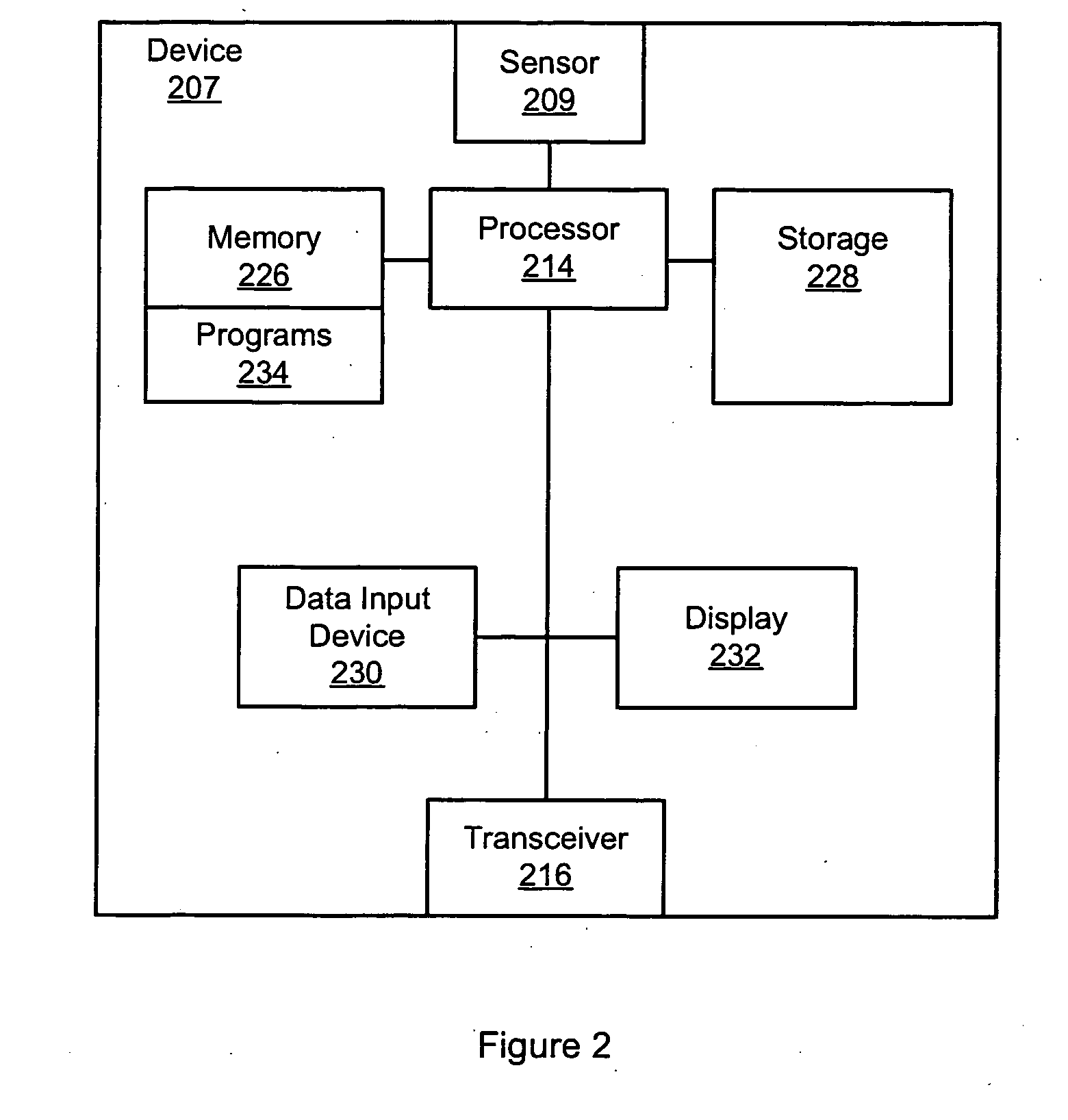
[0016] A wireless automation system configured for or using dynamic value reporting communicates data among and between devices related to changes in a value of a monitored condition and / or measured parameter (e.g., a wireless sensor for monitoring environmental temperature). A wireless automation device using dynamic value reporting monitors and wirelessly reports building automation information over a building automation network formed by multiple distributed devices. The distributed devices communicate information between and among the devices from a source device to a destination device.

[0017] A device that uses dynamic value reporting senses, samples and / or measures a condition during a period of a sampling or polling interval. A reading of the condition may be taken to identify an indicator associated with the current or present condition. The indicator of the current or present condition may be read during a current period of the sampling interval. The current reading of the...


PUM


Abstract

A wireless automation device monitors a condition and wirelessly reports an event over an automation network in response to detecting a change in the condition. The condition is sampled at a variable periodic interval, and the event reported during intervals when a change in the condition is determined. The change may be determined according to detecting a value for the condition outside a variable range. The change may also be determined according to detecting differences in the value from values detected in prior intervals. The range and the periodic interval may vary according to an analysis of multiple samples of the condition.

Description

BACKGROUND [0001] The invention relates to remote monitoring of conditions and more particularly to wirelessly reporting a sensed condition over a wireless communication network. [0002] Automation systems include one or more distributed components and / or grouping of components that together form an integrated system for automating a process control. The components include controllers, sensors, switches, alarms, actuators, chillers, fans, humidifiers, and / or air handling units configured to automate process control for heating, ventilation, air conditioning (HVAC), environmental air quality, safety and security, fire, hazard prevention, or other processes for a building or facility. The devices may communicate information over a wired network and / or by wirelessly broadcasting information between and among the components. [0003] The components may detect events, sense conditions, respond to detected events or changes in conditions, and / or control operation of other devices. An event m...

Claims


Application Information

Patent Timeline
Patent Type & Authority Applications(United States)
IPC IPC(8): H04L12/413
CPCH04L12/2803H04L67/12H04L12/2825Y04S40/18H04L12/413H04L65/40
Inventor MCFARLAND, NORMAN R.
Owner OLLNOVA TECH LTD
Why Eureka
Eureka Blog
Learn More